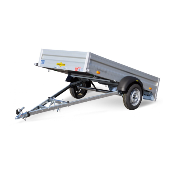
Page 1
OPERATING MANUAL PART 1 GENERAL CAR Program 1000 - 8400 SERIES humbaur.com...
Page 2
Humbaur GmbH Your trailer: Mercedesring 1 Model ___________________________________________________ 86368 Gersthofen Germany Type (abbreviation) ____________________________________________ Tel. + 49 821 24929-0 l info@humbaur.com Fax + 49 821 249-100 l www.humbaur.com Numberplate __________________________________________________ Trailer components: Axles(s) (Type / manufacturer) _______________________________________ Your dealer: Overrun device...
Page 3
Your entries Owner 1 Owner 2 Owner 3 First name, Last name First name, Last name First name, Last name Date of birth Date of birth Date of birth Address Address Address Street, House no. Street, House no. Street, House no. City City City...
Page 5
Notes on use PART 2 Obligations of the operator We would like to congratulate you on your new Humbaur You will find all the additional information on special The trailer may only be operated in perfect condition. trailer and thank you for the trust you have placed in us.
Contents Keyword index Use the keyword index from page 5 to search for 1 Safety 6 Electrical system specific topics. – from page 7 – from page 133 – Safety-relevant information – Lighting system Refer to the technical documentation of the installed components for additional information.
Page 7
Conditions for operating a trailer Handling ..........Jockey wheel ............Contact Body ..........Lubrication ..................Address Humbaur GmbH Chassis ........Numberplate light “LED" ............Humbaur Service Partners Height-adjustable drawbar (HV) ....... Overrun / deflection device ..........Parts logistics ............
Page 10
3. Presence of vehicle documents and type plate – Loading and unloading in a secured area or with vehicle or vehicle body after consulting Humbaur GmbH or additional safeguarding measures suitable for public – Carry the vehicle documents for your trailer with you.
Page 11
(e.g. chemicals, foodstuffs, hazardous goods). brakes, drawbar, hydraulic system, etc. by a layperson. Humbaur GmbH to be a structural change, and the type – Loading with a payload that is too heavy. As the manufacturer, we do not accept any liability approval therefore becomes null and void.
Page 12
– Unauthorised alterations to the trailer and the use of fittings – Defects as a result of an improper repair. not approved by Humbaur GmbH. These will invalidate the The warranty will not be valid if warranty. – Defects that can be attributed to structural alterations or –...
Page 13
Check, adjust and secure before each journey Sources of danger For trailers which can be tipped / lowered In the chassis area It is absolutely essential to comply with the following points: Note the following in general: – Standing under an unsecured cargo bed –...
Page 14
Signal words / warning signs / pictograms Safety first! Text sign Burn hazard! In this manual, you are informed about the different degrees You will find the following symbol in front of the text in the Hot surfaces. of risk as follows: manual: Signal words (arrow) Call to action...
Page 15
Signal words / warning signs / pictograms Personal protective equipment Mandatory signs Mandatory signs Wear the stipulated personal protective equipment (PPE) Keep to the following commands / calls for action for all the Keep to these prohibitions. for all the work described in this manual. work described in this manual.
Page 16
Signal words / warning signs / pictograms Other important pictograms Traffic signs regarding heights Pay attention to the following pictograms for proper disposal Pay attention to the following important traffic signs on as well as to provide first aid in an emergency. height limits on public roads.
Page 17
Stützlast eingehalten wird. perm. vertical load has to be adhered. 620.00404_A trailer. – Only use original HUMBAUR spare parts and Keep children well away when manoeuvring with the accessories. trailer. – Find out which accessories you are allowed to attach...
Page 18
General safety instructions While driving WARNING WARNING WARNING Excessive speed / speed not adapted! Unsecured / poorly secured load! Worn tyre profile / incorrect tyre pressure! The load could come loose and fall off - risk of snaking / The load can shift during the trip and could unbalance the The tyres can burst when driving along and the trailer will accidents! trailer or could be directly thrown off the trailer.
Page 19
General safety instructions During loading / unloading CAUTION CAUTION WARNING Non-compliance with the drawbar load! Inadequate / faulty lighting! Inadequate lighting! Exceeding the max. permissible drawbar load / not reaching It is difficult to see the trailer or it will not be seen in time by When loading / unloading, the lighting on the trailer could be the min.
Page 20
General safety instructions When parking WARNING WARNING Unsecured trailer! Trapped in the box body! The trailer can start moving out of control and could Risk of suffocation due to lack of oxygen. injure people - risk of accident! Secure the trailer against rolling away. ...
Page 22
Product description Basic components Car trailers Here you will find the basic components for a car trailer up to 3.5 to. 1 Ball coupling 2 Support bracket 3 V drawbar / drawbar frame 4 Jockey wheel 5 Safety cable (for braked) 6 Arrester cable (for braked) 7 Overrun device with hand brake lever, brake linkage, etc.
Page 23
(e.g.: TÜV, SGS). Confirmation of compliance Humbaur GmbH hereby attests to the company's compliance with all relevant EU directives for the registration and safe use of car trailers up to 3.5 to.
Page 24
Vehicle category: Length of the loading area: 2.700 mm If you lose the vehicle documents, you need to report it to 0.5. Name and address of manufacturer: Humbaur GmbH Rear overhang: 908 mm Mercedesring 1 the police. 86368 Gersthofen Masses...
Page 25
Vehicle identification Explanation of COC document Main dimensions Explanation of information The main dimensions can be found on the COC paper on Page 1 page 2 under the heading “Main dimensions”: – 01 Make, 02 Type of trailer, 0.2.1 Model –...
Page 26
Humbaur GmbH e1*2007/46*XXXX WHDXXXXXXXXXXXXXX 2000 kg 50 kg 1000 kg 1000 kg Humbaur GmbH Mercedesring 1 86368 Gersthofen GERMANY humbaur.com I - 023 I - 003 I - 001 I - 001 Fig. 17 Example: 2 type plates (France) Fig. 15 Example: Type plate, glued on Fig.
Page 27
Vehicle identification Component identification Overrun device Axle Drawbar I - 005 I - 010 I - 011 Fig. 21 Example: Sticker overrun device Fig. 24 Example: Type plate Knott axle, unbraked Fig. 27 Example: Lashing rail Accessories I - 006 I - 009 I - 012 Fig.
Page 28
Design variants / accessories Adapter Spare wheel / spare wheel holder Coupling protection I - 054 I 054 I - 014 I - 018 I - 018 Fig. 29 7 to 13 pin or 13 to 7 pin Fig. 32 Spare wheel holder with / without spare wheel Fig.
Page 29
Design variants / accessories Wheel chocks Lashing material Hydraulic system / cable winch I - 019 I - 021 I - 035 Fig. 38 Wheel chocks with retainers Fig. 41 Lashing belt set / car lashing set Fig. 44 Hydraulic system manual, electric / cable winch Anti-theft device Lashing points Loading ramps...
Page 30
Design variants / accessories Bodies / covers I - 037 I - 037 I - 040 Fig. 47 Flat cover on bodies / cover net Fig. 50 Rail 4-sides / 2- sides Fig. 53 Bicycle carrier / wood/aluminium cover with rail I - 038 I - 041 I - 041...
Page 32
Safety first! Commissioning the trailer General procedure Prerequisites for safe driving with a trailer: Requirements: To avoid accidents and prevent personal injury and material damage, it is important to Check the condition and functionality of the trailer before – The body must be fully closed while driving. setting off.
Page 33
Safety first! Departure check Components Testing Completed Ball coupling has engaged properly and is secured? Safety / wear indicator is in the green zone? Safety cable / arrester cable has been securely attached / hooked in to the retainer on the car coupling? Parking brake (if present) is released? Plug connection...
Page 34
(Un)coupling the trailer Trailer coupling on car / height of ball head coupling on trailer 430 ±35 B - 024 B - 025 B - 026 Fig. 2 Maximum swivel range of ball head coupling Fig. 3 The height of the ball head Fig.
Page 35
(Un)coupling the trailer Ball couplings Wear check Signs of wear B - 027 B - 028 B - 031 Fig. 5 Example: Ball couplings Fig. 6 Example: Ball coupling from below Fig. 7 Example: Optical display on the ball head coupling Handle Coupling cup Wear / safety indicator...
Page 36
(Un)coupling the trailer Coupling process B - 030 B - 033 B - 032 Fig. 8 Example: couple unbraked trailer Fig. 9 Example: coupled braked trailer Fig. 10 Example: coupled braked trailer Handle Wear / safety indicator Handle, secured Safety catch Handle, secured Safety catch, clicked in place Spherical cup...
Page 37
(Un)coupling the trailer Securing Uncoupling process B - 035 B - 034 B - 036 Fig. 11 Example: Lock handle Fig. 12 Example: uncouple unbraked trailer Fig. 13 Example: uncouple braked trailer Jockey wheel Handle, secured Handle Plug lock in barrier Safety catch Shackle lock in barrier Electrical plug...
Page 38
(Un)coupling the trailer Safety coupling (anti-snake coupling) A50-1 / 94/20/EG B - 109 B - 108 Fig. 14 Conditions for safety coupling Fig. 16 Example: ALKO AKS 3004-3504 Ball head (dirt / grease free, bare metal) Stabilising handle (for friction linings) B - 110 Coupling lever Fig.
Page 39
(Un)coupling the trailer Operating WS3000 safety coupling Operating AKS safety coupling Changing friction linings B - 112 B - 114 B - 115 Fig. 18 Position of WS3000 Fig. 19 Coupled positions of the AKS Fig. 20 Friction linings change Lashing straps Stabilisation handle closed Loose friction linings (made by Winterhoff)
Page 40
Loading / unloading Safety when loading / unloading To avoid accidents and to prevent personal injury and material damage, it is important to adhere to the correct sequence when loading / unloading. It is imperative to pay attention to the safety information! WARNING Loading / unloading the trailer without hitching...
Page 41
Loading / unloading Projecting load > 1 m B - 086 Fig. 23 Marking protruding loads to make them visible Sign / flag (30 cm x 30 cm) or cylindrical body (ø 35 cm x 30 cm) in bright red B - 087 B - 088 Fig.
Page 42
Loading / unloading Loading/unloading bulk goods WARNING Tipped cargo bed while unloading! A tipped cargo bed can fold down spontaneously. You may be struck/crushed/knocked. Keep people away from the tipped cargo bed during the tipping process. Do not stand or reach underneath a tipped cargo bed. ...
Page 43
Loading / unloading Stepping / driving on trailer B - 091 Fig. 28 Driving on trailer Drive-on tail gate B - 092 B - 093 NOTICE Fig. 29 Stepping on tipped cargo bed Fig. 30 Step onto cargo bed via loading ramps. Overloading the loading ramps / cargo bed! Loading bridge tipped Ramp / loading ramp / drive-up ramp...
Page 44
Loading / unloading Loading / unloading motorcycles B - 127 B - 128 B - 129 Fig. 31 Example 1: Transporting a motorcycle Fig. 32 Example 1: on tipper trailer Fig. 33 Motorcycle secured in the motorcycle stand Motorcycle stand Motorcycle stand Motorcycle stand Loading ramp...
Page 45
Loading / unloading Stepping onto a closed trailer body B - 094 B - 095 B - 096 Fig. 34 Operating the ramp wall Fig. 35 Operating double doors Fig. 36 Trailer which can be lowered with tail gate Ramp wall Double doors Tailgate Door holder...
Page 46
Loading / unloading Cable winch, manual B - 097 B - 098 B - 099 Fig. 37 Version 1: Cable winch, interchangeable Fig. 39 Version 2: Cable winch attached in middle Fig. 40 Version 3: Cable winch with pulley system Cable winch (secured in park position) Cable winch (operator setting released) Cable winch, at side...
Page 47
Loading / unloading Cable winch, electric B - 101 B - 102 - 105 Fig. 41 Example 1: Cable winch, fixed Fig. 43 Example 2: Adjustable cable winch Fig. 45 Example 2: Cable winch with remote control Cable winch with battery box Cable winch frame Remote control (drive) Front drop side...
Page 48
Load securing Load securing / loads Load distribution Distributing the load on the cargo bed To avoid accidents and to prevent personal injury CAUTION and material damage, it is important to carefully check the load distribution and how well it is Non-compliance with the drawbar secured.
Load securing Correct load distribution Incorrect load distribution Incorrect load distribution B - 063 B - 064 B - 065 Fig. 48 Load in axle area Fig. 49 Load too far forward (toward car) Fig. 50 Load too far back (at rear of trailer) –...
Page 50
Load securing Forces released Conclusion Tensioning forces – As the speed increases, it also increases the ~ 100 kg 0 km/h inertia forces / centrifugal forces of the load: 1. at 0 km/h = 100 kg kinetic energy 2. at 40 km/h = ~ 6000 kg kinetic energy 3.
Page 51
Load securing Load securing for transport Tie-down options Load securing is an important safety point when Tying the load across the drop sides or by wrapping WARNING transporting goods. Adhere to national and if around the chassis is prohibited! Unsecured / poorly secured load! applicable international regulations.
Page 52
Load securing Tie-down points in / on the cargo bed Tie-down points DIN Zurrpunkte B - 073 B - 075 Fig. 56 Tie-down brackets which can be recessed Fig. 58 Recessed tie-down points (optional) (kg) Tie-down force = max. 400 daN (kg) Version 1: Tie-down force = max.
Page 53
Lashing material B - 077 B - 078 B - 079 Fig. 60 Humbaur tie-down straps Fig. 61 Humbaur case sets Fig. 62 Application example: Humbaur lashing strap set Label (technical data) Car-Lashing Set Lashing strap Ratchet Lashing strap set...
Page 54
Load securing Tying down / securing the goods B - 081 B - 082 B - 083 Fig. 64 Negative example Fig. 65 Example: Load securing solid goods Fig. 66 Example: Load securing bulk goods Attached to chassis Tie-down point Material cones (gravel, sand, ballast, wood chips) Cover net Anti-slip underlay...
Page 55
Driving with the towing vehicle and trailer Driving with the towing vehicle and trailer B - 037 Fig. 67 Example: Driving with the towing vehicle and trailer Before setting off: While driving: Applying brakes: Carry out a departure check. ...
Page 56
Driving with the towing vehicle and trailer Driving at 100 km/h Circling / cornering Reversing B - 038 B - 039 B - 039 B - 040 Fig. 68 Maximum speed / 100 km/h sticker Fig. 69 Steering in / turning circle Fig.
Page 57
Manoeuvring Manoeuvring B - 060 B - 059 B - 061 Fig. 71 Manoeuvring with an unbraked trailer Fig. 72 Manual manoeuvring of the trailer Fig. 73 Manoeuvring with a braked trailer Underride protection Manoeuvring handle (optional) Automatic jockey wheel Drawbar Manoeuvring handle (optional) Coupling handle...
Page 58
Uncoupling / Parking Parking the trailer Avoid parking a trailer for a lengthy period when loaded. Parking a trailer without a towing vehicle in a public area (roads) is only permitted for a limited period of time. Please note: – Where possible park a trailer in a closed area or an area with a roof.
Page 59
Uncoupling / Parking Wheel chocks B - 042 B - 043 B - 116 Fig. 76 Example 1: Wheel chocks vertical at side Fig. 77 Example 2: Wheel chocks horizontal at side Fig. 78 Example 3: Wheel chocks vertical at front Wheel chock Wheel chock Bracket for wheel chock...
Page 60
Uncoupling / Parking Manipulating the wheel chocks B - 045 B - 046 B - 047 Fig. 80 Removing the wheel chock Fig. 81 Wheel chocks positioned Fig. 82 Secure the wheel chock (driving position) Lever Wheel chock Notch / lug Wheel chock Lever Holder...
Page 61
Uncoupling / Parking Hand brake / Parking brake B - 124 B - 125 B - 126 Fig. 83 Example 1: Hand brake released (driving position) Fig. 84 Hand brake applied / secured Fig. 85 Example 2: Hand brake released (made by BPW) Hand brake lever at bottom Hand brake lever at top Hand brake lever at bottom...
Page 62
Uncoupling / Parking Hand brake without push button B - 119 B - 118 B - 044 Fig. 86 Hand brake applied (made by Knott) Fig. 87 Releasing hand brake Fig. 88 Applying parking brake Hand brake lever at top Hand brake lever at bottom Hand brake lever Brake accumulator...
Page 63
Uncoupling / Parking Hand brake with push button B - 120 B - 122 B - 123 Fig. 89 Hand brake applied (made by ALKO) Fig. 91 Hand brake released Fig. 92 Applying parking brake Hand brake with push button at the top Hand brake lever at bottom Hand brake lever Gas strut...
Page 64
Uncoupling / Parking Drawbar support B - 048 B - 049 B - 050 Fig. 93 Trailer braked on drawbar support Fig. 94 Trailer unbraked on drawbar support Fig. 95 Trailer parked Drawbar support Retention strap Tyres Ring (as guide for safety cable) Drawbar support Wheel chock Safety cable...
Page 65
Uncoupling / Parking Long-term parking B - 054 B - 053 Fig. 96 Unbraked trailer Fig. 97 Braked trailer Drawbar support Tarpaulin (protects the cargo bed from getting waterlogged Wheel chocks positioned Wheel chocks positioned Hand brake released Jockey wheel wound up / parked B - 055 Overrun device covered (cover hood) Fig.
Page 66
Uncoupling / Parking Parking trailers in the winter / in the frost / bad weather B - 056 B - 057 B - 058 Fig. 99 Snow / ice on cargo bed Fig. 100 Box body Fig. 101 Covered trailer Cargo bed Roof with snow / ice load Tarpaulin...
Page 68
Legal requirements Safety notices / legal Attaching the arrester / safety cable incorrectly is Ball head couplings according to ECE-R55 DANGER dangerous and can result in fines in other countries! Driving with arrester / safety cable incorrectly attached! The arrester / safety cable could detach from the ball head while driving.
Page 69
Legal requirements Retrofitting a clamping device B - 006 B - 005 B - 007 Fig. 4 Example: Coupling according to old directive Fig. 5 Example: Clamping device on the coupling Fig. 6 Example: Clamping device on the coupling Coupling according to EEC 94/20 Universal clamping device, at front Universal clamping device, on side On older ball head couplings...
Page 70
Securing trailer to clamping device Securing elements Ball coupling (unbraked) Ball head coupling (braked) B - 009 B - 010 B - 011 Fig. 8 Overview of securing elements Fig. 9 Example: for unbraked trailer up to 750 kg GG Fig.
Page 71
Securing trailer to clamping device Securing trailer (unbraked) B - 013 B - 012 B - 014 Fig. 11 Attaching arrester cable Fig. 12 Arrester cable secured Fig. 13 Trailer uncoupled Lock, spring-loaded Hook, locked Arrester cable, tensioned in loop Arrester cable, threaded through Arrester cable, secured Support bracket...
Page 72
Securing trailer to clamping device Securing trailer (braked) B - 016 B - 015 B - 017 Fig. 14 Attaching safety cable Fig. 15 Safety cable secured Fig. 16 Trailer uncoupled Lock, spring-loaded Hook, locked Safety cable, tensioned in loop Safety cable with spring hook, threaded through Safety cable with spring hook, secured Hand brake, is applied...
Page 73
Securing trailer to clamping device Securing trailer (braked) - with snap hook B - 018 B - 019 B - 020 Fig. 17 Attaching safety cable Fig. 18 Safety cable secured Fig. 19 Trailer uncoupled Lock, spring-loaded Hook, locked Safety cable, tensioned in loop Safety cable with snap hook Safety cable with spring hook, secured Hand brake, is applied...
Page 74
Securing trailer to ring Securing with snap hook (according to DIN 5299) - directly B - 022 B - 021 B - 023 Fig. 20 Safety cable with snap hook Fig. 21 Example: Safety cable attached with snap hook Fig. 22 Example: Safety cable attached with snap hook Snap fastener Ball trailer coupling Ball trailer coupling...
Page 76
Support devices Jockey wheel F - 084 F - 028 F - 033 Fig. 1 Automatic jockey wheel (firmly attached) Fig. 2 Jockey wheel manual (to raise) Fig. 4 Example: Jockey wheel (pivoting) Jockey wheel Jockey wheel (on side of drawbar) Crank handle (fold in) Cylinder Screw clamp retainer...
Page 77
Support devices Jockey wheel in centre CAUTION Cranking up / raising the jockey wheel when the trailer is uncoupled! Drawbar could fall down and you can crush your hands / feet under the drawbar. Only crank up / raise the jockey wheel when the trailer is coupled to towing vehicle.
Page 78
Support devices Standard jockey wheel Lowering / cranking down Cranking up / raising F - 039 F - 037 F - 038 Fig. 10 Support position Fig. 11 Lowering jockey wheel Fig. 12 Position for driving Crank handle Cylinder Crank handle Cylinder T-handle Cylinder...
Page 79
Support devices Automatic jockey wheel Winding down Winding up F - 001 F - 041 F - 001 F - 040 F - 001 F - 029 Fig. 15 Crank down jockey wheel Fig. 16 Position for driving Fig. 13 Support position Crank handle Crank handle Crank handle...
Page 80
Support devices Jockey wheel, pivoting Pivoting in driving position Pivoting into support position F - 044 F - 043 F - 042 Fig. 18 Jockey wheel in driving position Fig. 19 Operating the jockey wheel Fig. 17 Support position Crank handle Crank handle Crank handle Cylinder...
Page 81
Support devices Supports – Supports are used to support your trailer when loading WARNING and unloading as well as when parking. Supports not in driving position before setting off! – From a load-capacity point of view, supports are not Supports could come loose or be ripped away when driving designed to lift a trailer.
Page 82
Support devices Height adjustment folding supports Distance from ground Height adjustment, telescopic crank supports ~ 4-6 cm F - 019 F - 025 F - 018 F - 018 Fig. 22 Air gap when loading Fig. 23 Telescopic crank supports, height-adjustable Fig.
Page 83
Support devices Prop stands Lowering Raising F - 004 F - 005 F - 002 Fig. 26 Lowering prop stands Fig. 27 Raising (driving position) Fig. 25 Prop stands (support position) Prop stand Weld spot Handle T-handle Prop stand Attachment console (clamps) T-handle ...
Page 84
Support devices Telescopic crank supports Lowering Raising F - 007 F - 008 F - 008 F - 006 Fig. 30 Crank down the telescopic crank support Fig. 31 Position for driving Fig. 28 Support position, secured Crank handle base Adjustable support Crank handle base Crank handle...
Page 85
Support devices Switchable telescopic crank supports Lowering Swivelling up F - 010 F - 011 F - 011 F - 009 Fig. 33 Telescopic crank supports, support position Fig. 34 Swivelling up support Fig. 32 Telescopic crank supports, driving position Crank handle base Plug pins Crank handle base...
Page 86
Support devices Telescopic crank supports which are switchable Lowering Swivelling up with a crank handle F - 023 F - 021 F - 024 F - 024 Fig. 36 releasing / lowering Fig. 37 Position for driving Fig. 35 Telescopic crank support with crank handle, support position Bracket lock Adjustable support...
Page 87
Support devices Corner legs (scissor struts) Lowering Raising F - 013 F - 014 F - 012 Fig. 39 Crank down the telescopic crank support Fig. 40 Telescopic crank supports, driving position Fig. 38 Corner leg, support position Crank handle base Adjustable support Corner leg Crank handle...
Page 88
Support devices Folding supports Folding down Swivelling up F - 017 F - 016 F - 015 Fig. 42 Folding down folding support Fig. 43 Folding support, driving position Fig. 41 Folding support, support position Adjustable support Adjustable support Fastening bracket Spring latch Spring latch Spring latch...
Page 89
Height-adjustable drawbar (HV) Height-adjustable drawbar (HV) Towing connection WARNING Drawbar height set incorrectly! The trailer could come uncoupled - risk of accident. Measure the height of the drawbar coupling. After adjusting and before tightening the T-handle, check the adjusted height again. WARNING T-handle not secured! The height of the HV drawbar can adjust itself.
Page 90
Height-adjustable drawbar (HV) Height adjustment F - 048 F - 049 F - 050 Fig. 46 Undo toggle locking switch Fig. 47 Adjust height Fig. 48 Hold in place and secure R-clip Handle R-clip Toggle locking switch Gearing Hole Toggle locking switch ...
Page 91
Height-adjustable drawbar (HV) Changing the towing connection F - 051 F - 052 F - 047 Fig. 50 HV drawbar maximum height Fig. 49 HV drawbar minimum height Fig. 51 Towing connection Overrun device Ball head coupling Lashing rail Through bore Towing ring Mounting bolt The towing connection can be replaced on an HV drawbar.
Page 92
Turntable / fifth wheel Turntable trailer (articulated drawbar) F - 076 F - 079 F - 077 Fig. 52 Turntable components Fig. 53 Turntable function Fig. 55 Example: 2-axles with box trailer body Wheels in size: R10C (10“) Front axle Turntable frame Turntable Prop stand...
Page 93
Turntable / fifth wheel Turntable as box body Turntable with pneumatic brake F - 078 F - 082 Fig. 57 Example: 2-axle as box body (Plywood) Fig. 59 Example: 3-axles as tarpaulin-covered body F - 083 F - 083 Fig. 61 Folding up drawbar Hand brake Drawbar ...
Page 94
Hydraulic system Hydraulic pumps DANGER WARNING Excessive operating pressure! Lines are under pressure! The maximum permissible pressure is exceeded. Lines The hydraulic line is under pressure when it is uncoupled. could burst / components will be damaged - risk of accident. The oil can escape under high pressure and cut people / ...
Page 95
Hydraulic system Manual hand pump (model 1) Manual hand pump (model 2) Electric pump with emergency hand pump F - 060 F - 061 F - 062 Fig. 63 Manual pump Fig. 65 Manual pump Fig. 66 Electric pump with emergency hand pump Pump lever Supply battery –...
Page 96
Loading ramps Ramps for vehicles F - 064 F - 066 F - 066 F - 068 Fig. 67 Example 1: Steel mesh ramp wall Fig. 69 Example 3: Loading ramps (steel) Fig. 71 Example 5: Loading ramp (aluminium) F - 065 F - 067 F - 06 F - 069...
Page 97
Loading ramps Using ramps – Ramps such as: Drive-up ramps / tracks, ramp walls CAUTION make loading and unloading easier. Operating ramps! – Ramps are designed to be suitable for the type of trailer When lowering / folding down / positioning the depending on the load.
Page 98
Loading ramps Securing ramps (driving position) F - 071 F - 072 F - 073 Fig. 74 Example: KFT, track ramps in driving position Fig. 75 Example: HA Allrounder, track ramps secured Fig. 76 Example: HT drive-up ramps secured Loading ramp Loading ramp Drive-up ramps Track guide...
Page 99
Toolbox Toolbox CAUTION Driving with unsecured toolbox! The lid could come open and tools could be catapulted out - risk of accident! Close the toolbox before driving off. CAUTION Overloaded toolbox! The holder could break - risk of accident! ...
Page 100
Toolbox Operating the toolbox (model 1) Operating the toolbox (model 2) F - 055 F - 054 F - 056 Fig. 79 Unlocking toolbox Fig. 80 Toolbox open Fig. 81 Using the toolbox Shackle lock Lock cylinder Lock Lock Lock Cover Opening ...
Page 101
Wheels / tyres Wheels / tyres WARNING Worn tyre profile / incorrect tyre pressure! The tyres could burst while driving – accident risk! The braking distance increases - risk of snaking! Regularly check the tyres. Check the tyre pressure, profile depth and condition of the tyres - see maintenance table.
Page 102
Spare wheel holder / spare wheel Spare wheel holder F - 090 F - 092 F - 093 Fig. 84 Spare wheel holder loose Fig. 86 Spare wheel holder on drop side Fig. 87 Spare wheel covered Holder (galvanised steel, for 4-bolt or 5-bolt rim) Spare wheel mounted Spare wheel cover The cover made of plastic (black) is available for wheel...
Page 104
Drop sides Drop sides in general Fig. 1 Drop sides Front drop side, folded down Comply with when handling: Side drop side Driving with unlocked / unsecured drop sides is not Rear drop side If the trailer is loaded, then relief the pressure from permitted! Stanchion the load if applicable before unlocking the drop...
Page 105
Drop sides Warnings in general A - 010 A - 011 A - 015 Fig. 2 Unsecured drop sides / stanchions Fig. 3 Covered lights Fig. 4 Crushing zone Stanchion Rear lighting Lock Cargo bed Rear drop side, folded down Drop side Rear drop side Stanchion...
Page 106
Drop sides Handling locks F - 004 A - 001 A - 002 Fig. 5 Tension lock (STEELY) Fig. 6 Tension lock (HU, HUK, HT, HTK) Fig. 7 Covered lock (STARTRAILER, HA, HT) Handle Handle Handle Securing device Tongue Access opening Bracket Strap Strap...
Page 107
Drop sides A - 003 A - 005 F - 006 Fig. 8 Angle lever lock (HTK, HT, box, horse) Fig. 9 Lug lock (ramp wall) Fig. 10 Ramp wall connection Ring Snap-lock Hook Locking latch Quick-release lever Locking spring Locking lever Eyelet Angle lever...
Page 108
Drop sides Handling drop side A - 008 A - 009 A - 012 Fig. 11 Open drop side (e.g. STARTRAILER) Fig. 12 Close drop side (e.g. HA, HT) Fig. 13 Removing the drop side Lock Lock Drop side Drop side Drop side Securing split pin Drop side hinge...
Page 109
Drop sides Flat-bed trailer A - 013 A - 014 A - 016 Fig. 14 Drop sides removed, stanchions removed Fig. 15 Inserting the stanchions Fig. 16 Drop sides mounted / secured Flat-bed trailer Stanchion Drop side Stanchion Stanchion pocket Hinge Stanchion pocket Locking lug...
Page 110
Side wall extension Side wall extension CAUTION Handling the side wall extensions! When handling / mounting / removing the side wall extensions you may crush your hands! Handle long side wall extensions with two people. Hold onto the side wall extensions firmly with both hands.
Page 111
Side wall extension Design versions (examples) A - 082 A - 083 A - 083 A - 084 A - 084 Fig. 19 Side wall extension (e.g. for HA) Fig. 21 Double side wall extension (e.g. for HT) Fig. 23 Side wall extension (e.g. for HA 500) A - 085 A - 085 A - 086...
Page 112
Side wall extension Fitting A - 090 A - 090 A - 092 A - 092 A - 092 Fig. 25 Fitting side wall extensions on side Fig. 26 Rear drop side / side wall extension removed Fig. 27 Fit rear / front side wall extension Side wall extension to the side Side wall extension on side (secured) Rear side wall extension...
Page 113
Front drop side extension Front drop side extension (examples) A - 094 A - 095 A - 113 Fig. 28 Aluminium slot-in partition wall Fig. 29 Steel mesh extension Fig. 30 Fixed front wall Lock Stanchion Front wall Aluminium slot-in partition wall Steel mesh Front drop side WARNING...
Page 114
H-frame H-frame A - 041 A - 042 A - 048 Fig. 31 Example: for HT, HU, HUK, HD Fig. 32 Example: STARTRAILER, STEELY, HA Fig. 33 H-frame secured H-frame, screwed version H-frame, welded version (2-part) Screw connection in stanchion WARNING Long loads must be secured as individual loading –...
Page 115
H-frame Securing a high load Securing a long load Load securing with H-frame A - 049 A - 051 Fig. 34 Load too high - risk of tipping over Fig. 36 Risk of collision with towing vehicle A - 039 A - 039 Fig.
Page 116
Rail Rail Tying down load A - 018 A - 017 A - 112 Fig. 41 Rail, 4 sides Fig. 40 Rail, 2 sides Fig. 42 Rail, 3-side (e.g. HKT lowering device) Rail Rail Rail Drop side Drop side Drop side The rail can be mounted retrospectively (side, front ...
Page 117
Flat cover Flat cover A - 021 A - 019 A - 022 Fig. 43 Lock 1 Fig. 44 Lock 2 Fig. 45 Lock 3 Elastic cable Flat ring Round ring Button Staple Tension rope Hook Hook Round ring U-bracket (for side wall extension, aluminium extension) The flat cover may only be used with closed drop –...
Page 118
Flat cover Flat cover with side wall extensions (examples) A - 026 A - 023 A - 027 Fig. 46 On side wall extension (HA, HT, HD) Fig. 48 On steel mesh extension Fig. 50 On aluminium extension A - 028 A - 024 A - 025 Fig.
Page 119
Flat cover Securing elements A - 038 A - 030 A - 035 A - 035 Fig. 52 Corner version: Elastic cable Fig. 54 Corner version: Staples Fig. 56 Corner version: Tension rope with hooks A - 032 A - 031 A - 036 Fig.
Page 120
Flat cover Positioning lateral bracing Handling the flat cover Fastening / duty rope (optional) A - 033 A - 037 A - 029 Fig. 58 Lateral bracing positioned Fig. 59 Pulling on flat cover Fig. 60 Fastening / duty rope lock as anti-theft device Side drop side Securing element Shackle lock...
Page 121
Tarpaulin cover Tarpaulin cover / roofbow A - 054 A - 053 A - 055 Fig. 61 Secured with a throwing cable / staples Fig. 62 Secured with a belt / elastic cable Fig. 63 Securing buckle / elastic cable Tarpaulin cover Tarpaulin cover Tarpaulin cover...
Page 122
Tarpaulin cover Warnings in general A - 057 A - 056 A - 058 Fig. 64 Open tarpaulin cover Fig. 65 Roofbow frame without tarpaulin cover Fig. 66 Example: Water load on tarpaulin cover Tarpaulin cover Roofbow frame Tarpaulin cover, not tensioned (water load) Roofbow frame / slot-in slats Lock unsecured WARNING...
Page 123
Tarpaulin cover Securing element Part 1 A - 059 A - 061 A - 063 Fig. 67 Throwing cable secured / unsecured Fig. 69 Belt secured / unsecured Fig. 71 Buckle secured / unsecured A - 060 A - 062 A - 064 Fig.
Page 124
Tarpaulin cover Securing element Part 2 Handling cover A - 065 A - 066 Fig. 73 Elastic cable corner version Fig. 75 Staples corner version A - 069 A - 069 A - 032 A - 031 Fig. 77 Rear wall / tarpaulin cover open Fig.
Page 125
Tarpaulin cover Slot-in slats (in U-profile) Slot-in slats (in roofbow pockets) A - 067 A - 068 A - 093 Fig. 78 Tarpaulin cover (e.g. HA) Fig. 79 Insert slot-in slat (e.g. HT) Fig. 80 Example: Trailer open Post U-profile Posts Slat inserted Slat...
Page 126
Tarpaulin cover Fastening rope (optional) Tarpaulin cover and ramp wall A - 072 A 072 A - 070 A - 071 Fig. 81 Fastening rope as anti-theft device Fig. 82 Tarpaulin cover open, ramp wall folded down Fig. 83 Tarpaulin cover closed (driving position) Rope end fastener Ramp wall connection Tarpaulin cover...
Page 127
Tarpaulin cover Tarpaulin cover with side sliding tarpaulin A - 073 A - 074 A - 075 Fig. 84 Tarpaulin cover / sliding tarpaulin closed Fig. 85 Rear wall / sliding tarpaulin open Fig. 86 Drop sides folded down Securing element Part 1 (throwing rope) Tarpaulin Slat insert Sliding tarpaulin...
Page 128
Tarpaulin cover Tarpaulin cover with Edscha cover A - 077 A - 078 A - 080 Fig. 87 Closed tarpaulin cover Fig. 88 Open rear wall Fig. 90 Slide open roof A - 076 How to handle the Edscha cover and the associated warning signs can be found in the manufacturers documents.
Page 129
Cover Wood / aluminium cover A - 104 A - 105 A - 105 Fig. 93 Cover attached at side Fig. 94 Loading process - from rear Cover open Gas strut Drop side folded down Piston retainer A - 103 Lock, locked + closed Fig.
Page 130
Bicycle stand Handling bicycle stand A - 099 A - 100 A - 101 Fig. 95 Mounted bicycle stand Fig. 96 Secure bicycle Fig. 97 Bicycle mounted / secured Rail Rotary handle, lockable Bicycle Bicycle stand Bracket support Belt Lateral bracing Frame Adjustable support –...
Page 131
Motorcycle stand Motorcycle stand A - 096 A - 097 A - 098 Fig. 98 Two motorcycle stands (example) Fig. 99 Motorcycle stand folded down Fig. 100 Motorcycle stand folded out / secured Drive-up ramp (example) Plug pins R-clip Loading ramp Wing nut Screw connection with wing nuts Drive-up ramp (as rocker)
Page 132
Cover net Cover net F - 043 F - 046 F - 046 A - 045 Fig. 101 Cover net secured Fig. 102 Example: Steel mesh extension Fig. 103 Application example Round button Elastic cable Cover net – Covers light garden waste / loose materials, e.g. leaves, With a steel mesh attachment, the cover net is attached to CAUTION small branches, wood chip, grass, paper, cardboard etc.
Page 133
Cover net Attaching cover net Removing / stowing cover net F - 106 F - 047 F - 107 Fig. 104 Secure cover net Fig. 105 Cover net tensioned Fig. 106 Stowing cover net Elastic cable Toolbox Round button Cover net Cover net Stowing away Removal...
Page 136
- if necessary, an adapter can be used. WARNING All of Humbaur trailers have 12 V safety lighting and a Damaged plug connections connector for the electric systems fitted as standard. Damaged, torn, porous plug connections can cause...
Page 137
Plug connections Cable / parking socket Cables are fed to the drawbar and are held in place by clamps. The plug is parked in the parking socket on the drawbar or on the coupling respectively. WARNING Damaged / torn cable connection Damaged, torn, worn, porous cable can impair the function or even cause the lighting system to fail - risk of accident! E - 007...
Page 138
Plug connections Adapter plug E - 027 E - 010 E - 009 Fig. 9 Test device plug (13-pin) Fig. 10 Adapter from 13 to 7 Fig. 12 Adapter from 7 to 13 contacts 13-pin contacts 7-pin contacts 7-pin contacts 13-pin Your towing vehicle can have a 7-pin or a 13-pin socket (depending on the vehicle).
Page 139
Contact configuration 7-pin plug connection Tab. 1 DIN ISO 1724 - 12 V Function Name Cross- Colour Figure / arrangement section Left indicator 1.5 mm² Yellow Rear fog light 1.5 mm² Blue Ground for contacts 1 - 7 2.5 mm² White Right indicator 1.5 mm²...
Page 140
If you have any problems with the electric system, contact a car dealer or a specialist workshop. Humbaur GmbH will not accept any liability or costs for consequential damage to the electric system of the towing vehicle and / or the trailer caused by incorrect configuration or reconfiguration of the contacts on the plug.
Page 141
Contact configuration Additional information for 13-pin plug configuration 9* Continuous current Trickle charge Under no circumstances clamp contact no. 10 to contact Towing vehicles without a socket according to DIN no. 9 in the plug. ISO 11446 do not normally have a cut-off relay. This could cause damage to the towing vehicle or the The result of this is: Damage to the car starter control electronics in the towing vehicle.
Numberplate light (white) Reversing light (white) - right version Check that the lights are all there, all around the trailer. The Humbaur GmbH multifunctional light can be used universally. Check them for damage and make sure that they work.
Page 143
Lighting system Clearance / Side / Marker lights E - 018 E - 019 E - 029 Fig. 19 Clearance / side lights at front Fig. 20 Clearance / side lights at rear Fig. 21 Side reflectors Reflector (white) front Marker light (red, white) top Reflector (white) front Side lights (white) front...
Page 144
230 V AC power supply Mains connection E - 022 E - 020 Fig. 24 Power distributor box Fig. 25 Example: Interior light 230 V Circuit breaker Linear light Potential equalisation / earthing Light switch E - 021 Maintenance work on the power distributor box Fig.
Page 146
Safety inspection Maintenance / Repair Proof of the HU/SP Maintenance of axles / wheels Duty to repair – Regular visual check / inspection of trailer and components looking for damage, dirt, wear. Handover - Service 10,000 km - Inspection 25,000 km - Inspection –...
Page 147
Electrical plug connection 11 Lashing points Jockey wheel 12 Supports Hydraulic system 13 Rear lights / marker lights Damaged and non-functioning trailer parts must be Hand brake exchanged for original spare parts of Humbaur GmbH. Drawbar Support bracket Testing, care and maintenance...
Page 149
Maintenance intervals Maintenance regime after One-off inspection / maintenance work Wheel bolts: Re-tighten (after every wheel change as well) Tyres: Check tyre pressure Braking system: Check the function of the overrun brake (carry out braking procedure) and adjust if necessary Wheel / tyre combination: Check sizes installed compared to COC paper / registration certificate Part 1 Lights: Check that all lights work and are present Coupling: Remeasure height of coupling head on towing vehicle and on the trailer...
Page 150
Maintenance intervals after Regular inspection / maintenance work Wheel bolts: check that they are tight and if necessary, tighten with a torque wrench (after every wheel change as well) Tyres: Check tyre pressure, set to recommended pressure Tyres / Wheels / Rims: Check general condition - Measure profile depth of tyres in the middle - Have old, brittle, worn tyres replaced - Have rims that wobble / are unbalanced / faulty balanced or replaced...
Page 151
Maintenance intervals after Regular inspection / maintenance work Supports: Check jockey wheel, support legs are working and are stable. - Lubricate jockey wheel at grease nipple and moveable parts - Check screw connections are tight - Have worn tyre on jockey wheel / deformed jockey wheel replaced Wheel shock absorber: Check for oil leakage and for firm fit - Replace faulty wheel shock absorbers in pairs - Check attachment points / screw connection for firm fit and tighten if required...
Page 152
Tyres/wheels Check tyres / wheels W - 009 W - 006 Fig. 7 Carry out inspection Fig. 8 Tyres / Technical information Profile depth Size Max. load / tyre pressure Wheels / tyres are important safety components on the Axles and suspension trailer.
Page 153
Tyres/wheels Tightening torque Check rims / attachment Rim material Tightening torque Nm (max.) Steel 100-110 Nm Aluminium 120 Nm Tab. 4 Tightening torques for wheel bolts On newly painted or new rims, the wheel bolts need to be tightened again after 20 operating hours! W - 011 W - 010 Fig.
Page 154
Tyres/wheels Check tyre condition Checking tyre pressure Tyre type max. in bar 18.5 x 8.5 - 8 145 / 80 R10 ; R13 155 R13 ; RF ; R13C 155 / 70 R12 ; R12C 6.25 155 / 70 R13 155 / 80 R13 W - 012 W - 013...
Page 155
Tyres/wheels Carrying a spare wheel On the V drawbar On the front wall (box) W - 015 W - 017 W - 014 Fig. 17 Example: Spare wheel on drawbar Fig. 19 Example: Spare wheel on front wall Fig. 16 Spare wheel (optional) Spare wheel External fixing plate Spare wheel complete...
Page 156
Tyres/wheels On the drop side On the chassis Check the spare wheel W - 019 W - 023 W - 021 Fig. 21 Example: Spare wheel on drop side Fig. 23 Example: Spare wheel on chassis Fig. 25 Check the spare wheel Spare wheel Spare wheel Valve (screwfit, on aluminium rim)
Page 157
Tyres/wheels Safety when changing the wheel A faulty tyre must be replaced immediately! Do not Important information on changing a wheel: WARNING take any safety risks! – Make sure that traffic is not obstructed when changing a Being under an unsecured trailer Disposing of tyres / wheels in the environment is wheel.
Page 158
Tyres/wheels Changing a wheel W - 025 W - 027 W - 026 Fig. 27 Secure trailer Fig. 28 Remove spare wheel Fig. 29 Jack up / support the trailer Wheel chocks Spherical collar nut (size 19) / spare wheel holder Axle tube / support area Spare wheel Support (jack)
Page 159
Tyres/wheels W - 028 W - 029 W - 030 Fig. 30 Pull faulty wheel off Fig. 31 Wheel hub without wheel Fig. 32 Fitting spare wheel Faulty wheel Wheel hub / contact surface (unbraked) Wheel bolts Wheel bolts Wheel hub with drum brake Torque wrench ...
Page 160
The undersigned R. Hartlieb (administrator) hereby certifies that the vehicle: (30 % of towing vehicle tare weight) 0.1. Make (Trade name of manufacturer): Humbaur 0.2. Type: HA EA G 1.1 for braked trailer (from 750 kg up to 3,500 kg)
Page 161
Wheel shock absorbers for 100 km/h Wheel shock absorbers W - 032 W - 033 W - 034 Fig. 36 Wheel shock absorbers - versions Fig. 37 Wheel shock absorber installed (version 1) Fig. 38 Wheel shock absorber installed (version 2) Extended shock absorbers Angle bracket on chassis Bracket on chassis...
Page 162
Lubrication Information on implementation Before lubricating After lubricating To lubricate / grease the components, only used the listed lubricants. Type of lubricant: – Multipurpose grease according to ISO-L-XCCHB3 or – according to DIN 51825 - Type K with application range: -30 °C to + 120 °C –...
Page 163
Lubrication Ball coupling Automatic jockey wheel W - 054 Fig. 43 braked: Top view W - 053 W - 056 Fig. 42 Ball coupling: Bottom view Fig. 45 Automatic jockey wheels: Lubrication points Safety indicator / mechanics Grease nipple Spherical cap Sliding point Coupling cup Bearing point / wheel...
Page 164
Lubrication Jockey wheel (manual) Handbrake (from 750 kg - 3.0 t) Handbrake (from 3.0 t - 3.5 t) W - 057 W - 059 W - 058 Fig. 46 Jockey wheels manual: Lubrication points Fig. 47 Brake: Lubrication points Fig. 48 Brake: Lubrication points Oil gap Hand brake lever / gas strut Brake accumulator...
Page 166
Lubrication Towing ring DIN 40 W - 100 W - 101 W - 102 Fig. 52 Towing ring Fig. 53 Dimensions Fig. 54 Lubricate towing ring Rounded area of towing ring D Diameter of wear bushing Screw bolts Wear bushing Thickness of towing ring Wear bushing Manufacturer label / technical values...
Page 167
Lubrication Turntable (fifth wheel) Drawbar (turntable trailer) Turntable brake W - 097 W - 098 W - 099 Fig. 55 Lubrication points on turntable Fig. 56 Drawbar lubrication point Fig. 57 Turntable brake lubrication point Turntable Grease nipple mounting bolts Gear Grease nipple Locking mechanism...
Page 168
Lubrication Telescopic support Prop stand Corner leg W - 062 W - 063 W - 064 Fig. 58 Supports: Lubrication points Fig. 59 Prop stands: Lubrication points Fig. 60 Corner legs: Lubrication points Grease nipple telescopic crank stand (can be swivelled) Cylinder body Square neck / bearing point Grease nipple telescopic crank stand (fixed)
Page 169
Adjusting overrun brake / wheel brake Checking setting of overrun brake Loosening brake linkage Setting / readjusting the wheel brake W - 089 W - 091 W - 090 Fig. 61 Overrun device Fig. 62 Example: Brake compensation Fig. 63 Example: Drum brake (ALKO) X Overrun travel / clearance Pull rod Stopper in inspection port for brake pad...
Page 170
Adjusting overrun brake / wheel brake Tensioning brake linkage Checking wear on brake pad Replacing brake pads Vehicle Technology QUALITY FOR LIFE INFORMATION l MANUALS l SERVICE W - 092 W - 093 EINBAU / AUSTAUSCH BREMSBACKEN Fig. 64 Example: Brake compensation tensioned Fig.
Page 171
Electrical system Maintaining electric systems / replacing bulbs W - 075 W - 07 Fig. 67 Check lighting The trailer is supplied with 12 V DC by the towing vehicle. Have all work on electrical installations carried out by qualified specialist staff. The outside / inside lighting must be checked during the annual inspection! The supply battery of the towing vehicle must...
Page 172
Clearance lights (stalk) W - 066 W - 067 W - 068 W - 068 Fig. 68 Humbaur tail light (horizontal) Fig. 69 Humbaur tail light (vertical) Fig. 70 Clearance light / stalk on rear 4x crosshead screws Tail light (left version)
Page 173
Electrical system Clearance light Clearance light - narrow Side light W - 069 W - 070 W - 071 Fig. 71 Clearance light / bulb at side on rear Fig. 72 Clearance light / bulb at side on rear Fig. 73 Side light / front bulb Cover glass (red, white) Cover lens (red, white) LED light (compact)
Page 174
Electrical system Side marker light Number plate light Reversing light W - 073 W - 074 W - 072 Fig. 75 Number plate lights, separate Fig. 76 Reversing light, separate Fig. 74 Side marker lights Light holder version 1 Light holder LED light (orange) Light holder version 2 Cover glass (white)
Page 175
Electrical system 3. Brake light strip Retro-reflectors / reflectors Interior lighting W - 076 W - 077 W - 095 Fig. 77 Brake light strip, separate Fig. 78 Retro-reflectors / reflectors Fig. 79 230 V AC / 12 V DC LED brake strip (for polyester body) Reflector side (orange) Linear light (230 V AC)
Page 176
WARNING Bei Fragen / In case of questions petroleum or mineral oils. Dirty trailer components / surfaces! service@humbaur.com Do not touch brake and hydraulic lines with sprays or 620.00508_A Dirty trailer components such as the ball head coupling, grease.
Page 177
Cleaning / care Safety while cleaning! WARNING NOTICE Cleaning / care products can be toxic! Using aggressive cleaning products People can injure or poison themselves, or given The surfaces / materials can be attacked by chemicals, themselves chemical burns if they come into salts, acids and bases.
Page 178
Cleaning / care High-pressure cleaner Cleaning the inside NOTICE Cleaning with a high-pressure cleaner! Components / surfaces which have a high-pressure jet aimed at them with too much pressure, when too close or with a water temperature which is too high could be damaged.
Page 179
Cleaning / care Ventilating / drying the inside Trailer materials Galvanised steel parts W - 085 Fig. 86 Galvanised surfaces Galvanised surfaces / components need to oxidise to prevent rust from developing. This can take several months. Once the surface loses its high gloss, a layer of rust protection has been formed.
Page 180
Cleaning / care Aluminium Painted and powder-coated steel parts Wooden components W - 086 W - 079 W - 080 Fig. 87 Aluminium, anodised Fig. 88 Painted surfaces Fig. 89 Wooden cargo bed / multilayer wooden plate Aluminium components or aluminium profiles offer optimal Painted surfaces / components provide slight rust Wooden floors / cargo beds are made of robust, water- protection against corrosion.
Page 181
Cleaning / care Caring for multi-layer wooden plate Plywood Sandwich panels (PurFerro) W - 103 W - 087 W - 081 W - 081 Fig. 90 Multi-layer wooden plate Fig. 91 Plywood plates (box bodies) Fig. 92 Sandwich panels (box bodies) Prevent the wooden surface swelling and oxidation with Plywood consists of several multi-layer wooden plates Sandwich panels consist of a polyurethane hard foam core...
Page 182
Cleaning / care Rubber / seals (silicone joints) Fabric tension cables (cords) Plastic tension cables (belts) W - 084 W - 084 W - 082 W - 083 Fig. 93 Sealing elements Fig. 94 Elastic cable Fig. 95 Plastic cable / belt Rubber parts such as elastic seals, sealing joints made of Elastic cables for tarpaulins consist of multiple rubber Fabric belts and buckles, plastic tension cables and their...
Page 183
Cleaning / care PVC / synthetic fabric Cleaning a tarpaulin with inscriptions on it: Polyester components (GRP) W - 049 W - 050 W - 048 Fig. 96 PVC tarpaulin Fig. 97 Inscriptions Fig. 98 GRP (glass fibre reinforced plastic) surfaces ...
Page 184
Decommissioning/disposal Decommissioning Disposing of operating materials Electrical and electronic scrap Trailers which are decommissioned (no longer Old oil, lubricants, coolants and refrigerants, Dispose of electrical and electronic components at your used) may only be parked on private property. fuel as well as batteries and rechargeable local recycling centre (electronic waste recycling).
Page 186
Humbaur GmbH can be reached. Humbaur GmbH. Your local Humbaur dealer can also provide expert advice Faults which occur as a consequence of failing to comply In both cases, please feel free to contact your local dealer.
Page 187
Load / Road handling Fault Possible causes Remedy The trailer pulls to the right or to left when driving along. The load is not evenly distributed. Distribute the load evenly. The tyre pressures are uneven. Set the tyre pressure on all wheels properly. ...
Page 188
Braking system Fault Possible causes Remedy Brakes smoking / do not release properly. Brakes are not properly adjusted. Have faults rectified by a specialist workshop. Brake callipers return spring slack / broken. Brake shaft jammed (drum brake). Cable or Bowden cable bent / deformed. Wheel brake is dirty / rusty.
Page 189
Ball coupling Fault Possible causes Remedy The coupling does not engage. Internal parts of the coupling (spherical cup, shell, spring) are Clean the components. dirty, frozen or not free-moving. Lubricate or oil the coupling. Ball head of the car coupling too large. Replace the car coupling (max.
Page 190
Tyres / Wheels / Axle Fault Possible causes Remedy The trailer squeaks as you drive along / worn bearing. Bearing setting too loose or too tight. Have faults rectified by a specialist workshop. Foreign body in axle bearing. Insufficient lubrication of axles.
Page 191
Shock absorbers / gas struts Fault Possible causes Remedy Components such as: Ramp wall/ doors / flaps which are Gas struts are too old - pressure has dropped. Replace the gas struts in pairs with new ones of the same supported with gas struts are no longer easy to raise / type.
Page 192
Lighting / power supply Fault Possible causes Remedy Trailer lighting is not working. Plug is not connected properly to the socket on the car. Plug in the plug until it reaches the end stop in the jack on the towing vehicle - also twist a 13-pin plug. Light / bulb is defective.
Page 193
Hydraulics Fault Possible causes Remedy Cylinder does not retract. A line or screw connection in the hydraulic system is faulty. Have the line / screw connection replaced in a specialist workshop. A screw connection in the hydraulic system is loose. ...
Page 196
Enter the identification data for your trailer. Have an inspection carried out every six months at the latest and have it confirmed in writing. Inspection intervals Purchase date:________________________________ VIN: WHD ____________________________________ Type: _______________________________________ 10,000 km - Inspection 25,000 km - Inspection Handover - Service Stamp / Signature Date...
Page 197
Inspection intervals 40,000 km - Inspection 55,000 km - Inspection 70,000 km - Inspection Stamp / Signature Date Stamp / Signature Date Stamp / Signature Date 45,000 km - Inspection 60,000 km - Inspection 75,000 km - Inspection Stamp / Signature Date Stamp / Signature Date...
Page 198
Notes Here is space for your notes: ______________________________________________ ______________________________________________ ______________________________________________ ______________________________________________ ______________________________________________ ______________________________________________ ______________________________________________ ______________________________________________ ______________________________________________ ______________________________________________ ______________________________________________ ______________________________________________ ______________________________________________ ______________________________________________ ______________________________________________ ______________________________________________ ______________________________________________ ______________________________________________ ______________________________________________ ______________________________________________ ______________________________________________ ______________________________________________ ______________________________________________ ______________________________________________ ______________________________________________ ______________________________________________ ______________________________________________ ______________________________________________ ______________________________________________ ______________________________________________ ______________________________________________ ______________________________________________ ______________________________________________ ______________________________________________ ______________________________________________ ______________________________________________...
Page 199
We wish you a pleasant & safe journey NOTES: ____________________________________________________ ____________________________________________________ ____________________________________________________ ____________________________________________________ ____________________________________________________ ____________________________________________________ ____________________________________________________ ____________________________________________________ ____________________________________________________ ____________________________________________________...
Page 200
All dimensions are approximate values and relate to the series vehicle without accessories. Printed in Germany. Reprint forbidden · Illustrations similar, some trailers show special Art. no. 007.00072 · Status: 07/ 2019 equipment · Images: Humbaur GmbH, fotolia.de ·...
Need help?
Do you have a question about the 1000 Series and is the answer not in the manual?
Questions and answers