
Related Manuals for Humbaur 2000 Series


Summary of Contents for Humbaur 2000 Series
- Page 1 Tandem trailers Operating MACHT’S MÖGLICH Instructions Part 2 - HA - HN - HT 2000 series...
- Page 2 It contains all the relevant details on safe operation, care/cleaning, maintenance/servicing, troubleshooting and decommissioning/disposal. This specific operating instruction manual (Part 2) for your trailer is provided on the enclosed CD. You can also download it from www.humbaur.com in the section: Download – Operating Instructions. PART 1 –...
-
Page 3: Table Of Contents
Index Identification Cleaning/maintenance/servicing 1.1 Confirmation of compliance 9.1 Care/cleaning 9.2 Maintenance/servicing Product description 2.1 Components 10 Troubleshooting 2.2 Flatbed trailers aluminium HA 2.3 Aluminium HN and HT wheels-in trailer 11 Decommissioning/disposal 2.4 Special versions 11.1 Shutdown 2.5 Optional accessories 11.2 Disposal Intended use 3.1 3.2 HN / HT Foreseeable misuse 4.1 4.2 HN / HT General safety instructions Loading and unloading 6.1 Load distribution 6.2 Load securing 6.3... -
Page 4: Identification
P ut a cross next to the type of trailer you have acquired. Humbaur GmbH hereby confirms compliance with all relevant EU directives for the registra- tion and safe use of trailers of the 2000 series tandem trailers ► ► Read the general operating instruction manual with accessories. -
Page 5: Product Description
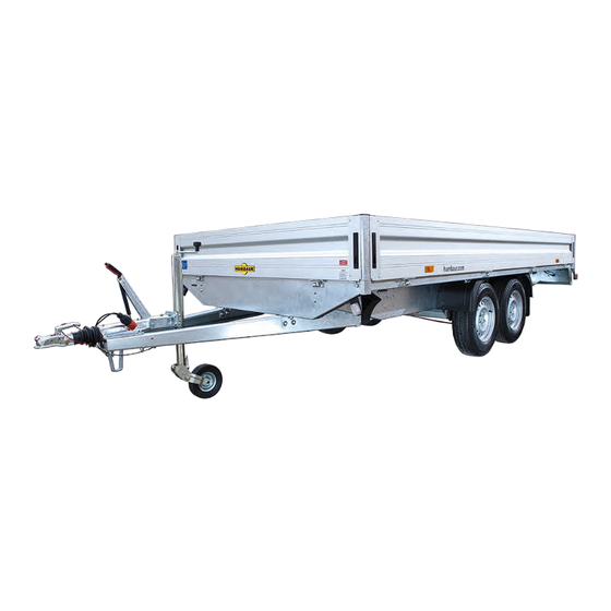
Product description 2.1 Components Illustrated examples Cargo bed Covered lock Hand brake lever Ball coupling Safety cable Drawbar support Parking socket electric systems / plug holder Jockey wheel V drawbar 10. Drop side hinge (HA) 11. Front drop side 12. Front reflector / side light 13. -
Page 6: Flatbed Trailers Aluminium Ha
2.2 Flatbed trailers aluminium HA 2.3 Aluminium HN and HT wheels-in trailer The HA is equipped with anodised aluminium drop sides. The HN/HT is equipped with anodised aluminium drop sides. The rear and side drop side can be folded down and removed. All of the drop sides can be folded down and removed. -
Page 7: Special Versions 7 11.1 Shutdown
2.4 Special versions Ramp wall with tarpaulin cover Vehicle transporters HN with aluminium checker plate, rear view Ramp wall rear view Tarpaulin cover without drop sides HN with cable winch frame, front view Long drawbar 1333 Tarpaulin cover without drop side 1621 3-axle trailer HN / HT with long drawbar, side view... -
Page 8: Optional Accessories 8 11.2 Disposal
2.5 Optional accessories H-frame Side wall extension Drawbar toolbox HN/HT toolbox Wood/aluminium cover Rail Drawbar spare wheel Side spare wheel Cover net Two-part drop side Prop stand Telescopic prop stand Flat cover Tarpaulin + frame Steel mesh extension Aluminium checker plate Aluminium drive-up ramp Grid ramp wall Lashing ring... -
Page 9: Intended Use
Intended use General safety instructions • Transport of goods, with the exception of hazardous goods, e.g., explosive, chemical or liquid materials. Observe the other general safety recommendations in • Transport of fixed and loose loads. the operating instruction manual, “Trailers up to 3.5 to” •... -
Page 10: Loading And Unloading
Loading and unloading 6.2.1 Loading/unloading the trailer CAUTION Folding ramp wall The trailer must be secured so it cannot roll away. After unlocking, the ramp wall can fall down uncontrollably, e.g., from load pressure – impact risk! This can result in feet being crushed. ► ► Stand to the side when unlocking the ramp wall. ►... -
Page 11: Load Securing
6.2 Load securing Correct load distribution For relevant safety information for load securing, refer to the section “General load securing” in the operating instruction manual “Trailers up to 3.5 to – General part 1.” WARNING Unsecured load! The load can be thrown around during the journey. The trailer may start to lurch –... - Page 12 6.2.1 Projecting load In Germany, goods that project over the cargo bed or drop sides must be marked in accordance with Section 22 of the StVO (German Road Traffic Act). > 1 m Marking goods Sign/flag (30 cm x 30 cm) or cylindrical body (ø 35 cm x 30 cm), bright red Secured with tie-down ►...
- Page 13 6.2.2 Tie-down points Tying down goods Optional/additional tie-down points Tie-down ring recessed in tie-down groove, in loading platform (tie-down force = max. 400 or 200 daN (kg)) HA - tie-down points (tie-down force = max. 400 daN (kg)) Loading platform Tie-down brackets, recessed Side drop side Optional/additional tie-down points...
-
Page 14: Drop Sides
6.3 Drop sides WARNING Driving with the rear drop side folded down! Any rear lights are covered. The trailer cannot be seen in traffic – danger of accident! ► ► Remove the rear drop side when driving with a load projecting to the rear. - Page 15 Taking off the drop side Drop side hinge release Securing split pin Drop side hinge Drop side Rear drop side, folded down ► ► Remove the securing split pin from the drop side hinge. Rear drop side, folded down ► ►...
- Page 16 Drop sides removed, stanchions removed Putting on the drop side ► ► ► ► Store the stanchions/drop sides safely to prevent damage. Hold the drop side in about the middle lengthwise. ► ► Slide the drop side onto its hinges in a horizontal position. Fitting the drop sides Stanchions inserted Securing the drop side...
- Page 17 6.3.2 Drop side – HA Removal Functional explanation • The front and rear drop side can be removed when transporting long cargo. • The front and rear drop side can be folded down, depending on the loading/unloading process. ► ► Instructions for operating (opening/closing) the drop sides are provided in the Drop side –...
-
Page 18: Side Wall Extension (Optional)
6.4 Side wall extension (optional) 6.3.3 Rear drop side with support rope (optional) Functional explanation Functional explanation • The rear drop side can be held open in a horizontal • The side wall extension (350 mm) increases the loading position by means a support rope. volume of the trailer. -
Page 19: Two-Part Drop Side (Optional)
6.5 Two-part drop side (optional) Removal Functional explanation • The HN and HT trailers are optionally available with a two- part main drop side with a centre stanchion. • A two-part side wall extension with centre stanchion is available. ► ►... -
Page 20: Raised Drop Side (Optional)
6.6 Raised drop side (optional) 6.7 Steel mesh extension – HA (optional) Functional explanation Functional explanation • The HA, HN and HT trailers can optionally be equipped • HA trailers can be optionally equipped with a steel mesh with a raised drop side of 500 mm. extension. -
Page 21: Supports (Optional)
6.8 Supports (optional) 6.8.2 Prop stands 6.8.1 Telescopic prop stands – HN/HT Functional explanation • As an option, the prop stands are available loose or as Functional explanation fitted accessories. • HN / HT trailers can be optionally equipped with swivelling •... -
Page 22: Wood/Aluminium Cover (Optional)
6.9 Wood/aluminium cover (optional) Functional explanation • The wood/aluminium cover is used for the protected transport of sensitive goods. • The wood/aluminium cover can be locked with a key and thus protects your goods against theft. • The loading volume is increased by the internal height of the wood/aluminium cover, i.e., by 185 mm. - Page 23 Operating the cover Opening Cover open ► ► Take hold of the handle and lift the cover. - The gas struts assist in opening the cover ► ► Hold the cover open as far as it will go. Closing Wood/aluminium cover Cover Lock Handle...
- Page 24 Cover with rail Bicycle stand Functional explanation The rail must be equipped with 2 lateral crossbars when • The cover with a rail may be used as an additional cargo using a bicycle stand. bed for light loads. • The rail on the cover is used to transport and secure loads Read and observe the assembly instructions.
-
Page 25: Flat Cover (Optional)
6.10 Flat cover (optional) 6.11 Tarpaulin cover (optional) Functional explanation Functional explanation • In addition to the flat cover, trailers also receive one or two • Trailers can optionally be fitted with a tarpaulin cover and lateral bracings. a frame. •... - Page 26 Tarpaulin cover with belt Closing Tarpaulin cover/frame with belt Tarpaulin cover closed / secured Belt Buckle Tarpaulin cover Staple Staple ► ► Close the rear drop side. ► ► Roll up the tarpaulin cover. ► ► Secure the tarpaulin cover at the rear with the staples. ►...
- Page 27 6.11.1 Swing-out frame Opening Functional explanation • The frame makes it easier to operate and open the cover parts. • Side and rear cover parts can be swung open. Frame clip Released Lever Bolt Bracket ► ► Release the bolts on both sides. ►...
- Page 28 6.11.2 Lateral sliding tarpaulin 6.11.3 Tarpaulin cover without drop side Functional explanation Functional explanation • The side cover parts can be slid open. • The tarpaulin cover can be fitted and secured directly to the chassis. Tarpaulin cover with side sliding tarpaulin Tarpaulin cover without drop side, closed Tensioning rope Sliding tarpaulin...
-
Page 29: Ramp Wall - Hn/Ht (Optional)
6.12 Ramp wall – HN/HT (optional) Functional explanation • The ramp wall allows the cargo to be loaded with forklift or rolling containers, for example. WARNING Ramp wall overloaded! The ramp wall may become deformed or break. The goods/vehicle to be loaded may tip over – risk of crushing! ►... - Page 30 Unlocking locks WARNING Unsecured angle lever locks! The ramp wall could burst open while driving – accident risk! ► ► Check that all angle lever locks are secured with locking springs before driving off. ► ► Position yourself on the side next to the ramp wall before unlocking the angle lever lock.
-
Page 31: H-Frame (Optional)
6.13 H-frame (optional) Closing Functional explanation • The H-frame is inserted into the front stanchions and secured. • The H-frame is used to transport and secure long loads. Read and observe the assembly instructions. Long loads must be secured as individual loading units. It is not permitted to drive with loose loads on the H-frame. -
Page 32: Drive-Up Ramp - Hn / Ht (Optional)
6.14 Drive-up ramp – HN / HT (optional) Functional explanation WARNING • The drive-up ramps are made of aluminium and 2230 mm or 2650 mm long depending on the trailer. Drive-up ramps not secured! • The drive-up ramps are available as fitted accessories. The drive-up ramps can slip off from the cargo •... - Page 33 Removal Removing the drive-up ramps Square key Supporting the trailer Ramp slot cover ► ► Open the rear drop side and carefully fold it down. Keyhole ► ► Place the telescopic prop stands underneath. ► ► Release the ramp slot cover. ►...
- Page 34 Positioning Drive-up ramps positioned Drive-up ramps positioned Locking strap Driving up Gap between chassis and rear drop side ► ► Lift the drive-up ramp with both hands. It is only permitted to drive up the drive-up ramps if the driver can see the wheels directly. ►...
-
Page 35: Cable Winch (Optional)
6.15 Cable winch (optional) Stowing/securing Functional explanation • The cable winch is located centrally or laterally on the drawbar. • Defective vehicles can be pulled onto the cargo bed using the cable winch. 6.15.1 Cable winch Setting down/re-inserting the drive-up ramps Stopper Locking strap ►... - Page 36 Preparing the cable winch WARNING Using a damaged cable winch A damaged cable will be weakened and may tear when placed under load. People could be hit or crushed by the cable and/or the load. ► ► Only use the cable winch if it is undamaged and in per- fect condition. ► ► Have the cable winch regularly serviced and repair it immediately if it is faulty.
- Page 37 Folding down the drop side Extending/unrolling the cable ► ► Manually extend the cable. - Ensure that the crank handle turns. - If necessary, remove the crank handle beforehand. Securing/winching the load Amongst others, the loader is responsible for securing the load with tie-down devices! Winching the load/vehicle is the most dangerous phase during operation of the cable winch!
-
Page 38: Grid Ramp Wall - Ha (Optional)
6.16 Grid ramp wall – HA (optional) Functional explanation CAUTION • The grid ramp wall allows vehicles to be loaded. Unlocking the grid ramp wall Grid ramp wall can fall down uncontrollably – risk of impact/crushing! ► ► Keep firm hold of the grid ramp wall when unlocking it. ►... - Page 39 Opening/folding down Driving up Unlocking locks Grid ramp wall – as an even driving surface ► ► Unlock the lock on the drop-side side without handles on The cargo bed may only be loaded when the trailer is the grid ramp wall. hitched.
- Page 40 Folding up/locking Grid ramp wall folded up Securing the grid ramp wall ► ► Push the quick-release lever shut. This must engage with the snap lock. ► ► Hold the grid ramp wall firmly at the handles with both ► ►...
-
Page 41: Toolbox (Optional)
6.17 Toolbox (optional) 6.17.2 Toolbox – HN / HT Functional explanation • The trailer can be optionally equipped with a toolbox that can be used to store tools and accessories, such as cleaning equipment, tie-down equipment, etc. • The toolbox is mounted to the side on the chassis in the HN and HT versions. -
Page 42: Driving
Manoeuvring options Your trailer can be licensed for a top speed of max. 100 kph. For this, several conditions must be fulfilled. Manoeuvring is only permitted when the trailer is not - For information, see www.humbaur.com loaded. ► ► Adapt your driving style to the road and weather... -
Page 43: Cleaning/Maintenance/Servicing
Cleaning/maintenance/servicing Using wheel chocks 9.1 Care/cleaning Observe the safety instructions for operating wheel chocks in the operating instruction manual, “Trailers up to 3.5 to – ” General PointsPart 1. Observe the safety instructions and instructions for general cleaning/care of trailers in the operating CAUTION instruction manual, “Trailers up to 3.5 to”... - Page 44 9.2.2 Gas struts • The gas struts are intrinsically maintenance-free. • However, the gas struts are subject to wear that can be reduced by regular maintenance. The working range of the gas struts is: - 25 °C to + 60 °C. Service life, functionality and safety depend largely on ensuring that the gas struts are serviced regularly.
-
Page 45: 10 Troubleshooting
10 Troubleshooting Malfunction Possible cause Solution Cover with gas struts can no - Gas struts are too weak. Have the gas struts replaced in a specialist longer be easily lifted. workshop. - The gas struts are defective. Ramp wall can only be lifted - Gas struts are too weak. - Page 46 Humbaur wishes you a pleasant & safe journey! Notes ► ► ________________________________________________________________________________________________________ __________________________________________________________________________ __________________________________________________________________________ __________________________________________________________________________ __________________________________________________________________________ __________________________________________________________________________ __________________________________________________________________________ __________________________________________________________________________ Version 2019/01 Tandem HA, HN & HT Operating Instruction Manual (Part 2)
- Page 47 Tandem HA, HN & HT Operating Instruction Manual (Part 2) Version 2019/01...
- Page 48 MACHT’S MÖGLICH We assume no responsibility for printing or other errors or omissions. All illustrations are representative. Deviations and modifications are subject to the model type. Subject to technical modifications. Copying prohibited. Printed in Germany. Version 2019/01...
Need help?
Do you have a question about the 2000 Series and is the answer not in the manual?
Questions and answers