
Related Manuals for A-Neuvideo ANI-HDROTATE-PLUS

Summary of Contents for A-Neuvideo ANI-HDROTATE-PLUS
- Page 1 ANI-HDROTATE-PLUS 2x1 UHD+ HDMI VIDEO WALL ROTATION PROCESSOR AUDIO / VIDEO MANUFACTURER A-NeuVideo.com Frisco, Texas 75036...
- Page 2 SAFETY INFORMATION 1. To ensure the best results from this product, please read this manual and all other documentation before operating your equipment. Retain all documentation for future reference. 2. Follow all instructions printed on unit chassis for proper operation. 3.
- Page 3 NEUVIDEO SAFETY PRECAUTIONS Please read all instructions before attempting to unpack, install or operate this equipment and before connecting the power supply. Please keep the following in mind as you unpack and install this equipment: • Always follow basic safety precautions to reduce the risk of fire, electrical shock and injury to persons. •...
-
Page 4: Table Of Contents
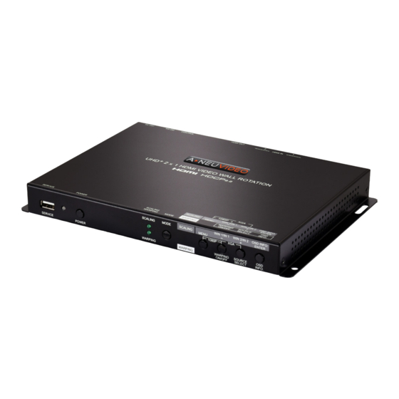
CONNECTION DIAGRAMS......................59 INTRODUCTION The ANI-HDROTATE-PLUS UHD+ 2x1 HDMI Video Wall Rotation processor is capable of scaling and rotating the selected input source to nearly any angle and size desired. It’s the ideal solution for presenting sources across the unique video display arrangements often found in commercial displays, control rooms, or classrooms. -
Page 5: Features
FEATURES / APPLICATIONS / SYSTEM REQUIREMENTS FEATURES • HDMI 2.0 and DVI 1.0 compliant (with the use of an HDMI-DVI adapter) • HDCP 1.x and 2.2 compliant • (2) HDMI inputs and (1) HDMI output • Supports up to 4K UHD+ (18Gbps, 4K@50/60Hz 4:4:4, 8-bit) video input and output •... -
Page 6: Specifications
SPECIFICATIONS • HDMI Bandwidth: 18Gbps • Input Port: (2) HDMI (Type-A) • Output Port: HDMI (Type-A) • Control Ports: RS-232 (3.5mm) & IP Control (RJ-45) • Service Port: USB 2.0 (Type-A) • Baud Rate: 19200 • Power Supply: 24V/2.7A DC (US/EU standards, CE/FCC/UL certified) •... -
Page 7: Front Panel
PANEL DESCRIPTIONS FRONT PANEL q SERVICE PORT: This port is reserved for firmware update and user EDID/logo upload use only. w POWER LED: This LED will illuminate green to indicate the unit is on and receiving power. When the unit is in stand-by mode the LED will illuminate red. e POWER BUTTON: Press this button to power the unit on or place it into stand-by mode. -
Page 8: Back Panel
PANEL DESCRIPTIONS BACK PANEL q HDMI IN 1~2 PORTS: Connect to HDMI source equipment such as media players, game consoles, or set-top boxes. w HDMI OUT PORT: Connect to an HDMI TV, monitor, or amplifier for digital video and audio output. e CONTROL PORT: Connect directly, or through a network switch, to your PC/laptop to control the unit via the control software or Telnet. -
Page 9: Rs-232 Protocol / Audio & Cable Specifications
RS-232 Protocol / Audio & cable Specifications RS-232 Protocol Serial Port Default Settings BAUD RATE 19200 DATA BITS PARITY BITS None STOP BITS FLOW CONTROL None Audio Specifications HDMI INPUT/OUTPUT LPCM Max Channels 2 Channels Sampling Rate (kHz) BITSTREAM Supported Formats None cable Specifications CABLE LENGTH... -
Page 10: Osd Menu
OSD Menu All functions of this unit can be controlled by using the OSD (On Screen Display) which is activated by pressing the MENU button on the front of the unit. Use the + (PLUS), − (MINUS), and ENTER buttons to navigate the OSD menu. Press the MENU button to back out from any menu item and then press it again to close the menu. - Page 11 OSD Menu 2ND LEVEL 3RD LEVEL Video Mode Preset 3 cont’d Preset 4 Out Source (Switcher Only) IN 1 In 2 Win 1 Source (Pip/PoP/Preset) IN 1 In 2 Win 2 Source (Pip/PoP/Preset) In 1 IN 2 Warping Mode Warping Preset WARPING Preset 1 Preset 2...
- Page 12 OSD Menu 5. Warping Preset: Select the warping preset to configure. Note: All changes made to the video/audio output configuration are automatically saved to the currently selected preset. 6. Output Source: Select the source for the HDMI output while in Warping mode. 7.
- Page 13 OSD Menu 2ND LEVEL 3RD LEVEL Border On/Off Border Color Black GREEN Blue Yellow Magenta Cyan White Dark Red Dark Green Dark Blue Dark Yellow Dark Magenta Dark Cyan Gray 1. Window Select: Select the window to modify. Note: Only available in multi-windowing modes. All settings are individually saved, per-window/per- mode.
- Page 14 OSD Menu 6. Aspect Ratio: Select a fixed aspect ratio for the currently selected window. The aspect ratio will be based on the window’s current height. Selecting the “Full” aspect ratio will return the window to the current mode’s default size and shape for that window. Selecting “Best Fit” will automatically set the ratio based on the window’s current source resolution.
- Page 15 OSD Menu 1. Warping Select: Displays which warping preset is currently active. 2. Keep Aspect Ratio: Enables or disables forcing the current aspect ratio to be maintained when the display is resized by changing the warping width or height. 3. Warping Left/Top: Sets the pixel position of the top/left corner of the pre-rotated display within the currently selected source.
- Page 16 OSD Menu 2ND LEVEL 3RD LEVEL Reset 1. Input Select: Select the input to modify. 2. Contrast: Set the overall contrast of the currently selected input. 3. Brightness: Set the overall brightness of the currently selected input. 4. Saturation: Set the overall saturation of the currently selected input. 5.
- Page 17 OSD Menu 2ND LEVEL 3RD LEVEL All EDID 4Kp60 2CH cont’d Sink OUT User 1 User 2 User 3 User 4 IN 1 EDID [Same as All EDID] IN 2 EDID [Same as All EDID] User 1 Update User 2 Update User 3 Update User 4 Update 1.
- Page 18 OSD Menu HDCP MODE 2ND LEVEL 3RD LEVEL In 1 HDCP Support Off Refer to Source REFER TO DISPLAY In 2 HDCP Support Off Refer to Source REFER TO DISPLAY - HDCP Status - Win 1 [Current HDCP Status] Win 2 1.
- Page 19 OSD Menu 2ND LEVEL 640x480p59 1920x1080p25 480p60 1920x1080p30 576p50 1920x1080p50 800x600p60 1920x1080P60 848x480p60 1920x1200rb 1024x768p60 2048x1152rb 1280x720p50 3840x2160p24 * 1280x720p60 3840x2160p25 * 1280x768p60 3840x2160p30 * 1280x800p60 4Kp24 (DCI) 1280x960p60 4Kp25 (DCI) 1280x1024p60 4Kp30 (DCI) 1360x768p60 4Kp50 (DCI) 1366x768p60 4Kp59 (DCI) 1400x1050p60 4Kp60 (DCI) 1440x900p60...
- Page 20 OSD Menu 2ND LEVEL 3RD LEVEL Menu Position cont’d Bottom Left Menu Timeout 5~60 (10) Info. Timeout 5~60 (5) Info. Display Transparency 0~15 (5) Background Black GRAY Blue 1. Menu Position: Set the position of the OSD menu on the output. 2.
- Page 21 OSD Menu 2ND LEVEL 3RD LEVEL Load Default Logo cont’d Logo Update 1. Logo On/Off: Enable or disable displaying the logo graphic. 2. Position X/Y: Sets the position of the logo’s upper left corner, within the output. The position values are a relative percentage of the available output resolution. Note: When Warping mode is active the logo will remain aligned with the physical display and will not be rotated or scaled with the source video.
- Page 22 OSD Menu 2ND LEVEL 3RD LEVEL MAC Addr. [Unit’s MAC Address] 1. IP Mode: Set the unit’s IP address mode to Static or DHCP. 2. Static IP Config: When the unit is in Static IP mode the IP address, netmask and gateway addresses may be manually set here.
- Page 23 OSD Menu 2ND LEVEL 3RD LEVEL Auto Sync Off 15 sec cont’d 30 sec 1 min 1.5 min 2 min 2.5 min 3 min 5 min 10 min Auto Source Telnet TimeOut 1~10 mins Firmware Update User EDID Reset Factory Reset 1.
- Page 24 OSD Menu 5. User EDID Reset: Select “Yes” to reset the unit’s User EDIDs to their factory default states. 6. Factory Reset: Select “Yes” to reset the unit to its factory default state. After the reset is complete, the unit will reboot automatically. INFORMATION 2ND LEVEL 3RD LEVEL...
-
Page 25: Video Wall Control Software
Scaling mode of the unit, if needed. Softw are Operation You can download the “Video Wall Control” software from the A-NeuVideo product page. Ensure that all the units you wish to control have been powered on and that they are all connected to the same network as your laptop/PC. - Page 26 Video W all Control Softw are Video W all Unit Search By clicking on the “Search” button at the top-right corner of the window, all Video Wall Rotation Pocessors that are located on the local network or are directly connected via RS-232 can automatically discovered.
- Page 27 Video W all Control Softw are 2. Connect Button: Clicking the “Connect” button will activate the software’s connection to all currently selected units, allowing control and configuration of those units. To connect a display to only a single unit, right click on the display’s number and select “Connect” from the dropdown menu. 3.
- Page 28 Video W all Control Softw are Basic Unit Settings & Configuration The basic configuration and settings for each connected unit can be set by selecting the unit to configure from the “Units” section and then clicking on the “Setting” button in the upper-left “Common”...
- Page 29 Video W all Control Softw are I/O Configuration The “I/O” tab provides control over basic input and output functions such as EDID selection, audio mute, OSD Information, and the custom logo overlay. To return these settings to their factory defaults, click on the “Default”...
- Page 30 Video W all Control Softw are 8. OSD Info Auto Sync Timeout: Set the length of time, in seconds, that the informational OSD will be displayed after a signal or source change, or disable the timeout completely. 9. OSD Menu Display: Selecting “On” will force the menu to appear on screen. 10.
- Page 31 Video W all Control Softw are Scaling Mode Image Configuration The “Image” tab in Scaling mode provides control over the video color and quality settings for each input on the unit. To return these settings to their factory defaults, click on the “Default” button. Changes made to these settings will occur immediately.
- Page 32 Video W all Control Softw are Scaling Mode La youts The position and size of up to 2 windows on the selected unit can be configured in the Layout window’s Scaling tab when in Scaling Mode. If you are currently in the Setting window, clicking on the “Layout”...
- Page 33 Video W all Control Softw are • ID: Displays the ID number of the currently selected window. • Left/Top: Sets the X and Y coordinate position of the upper left corner of the currently selected window. Click on the “Set” button, after making changes, to make them active. •...
- Page 34 Video W all Control Softw are W arping Mode La youts The position, size and angle of the display connected to each unit is set in the Layout window’s Warping tab when in Warping Mode. If you are currently in the Setting window, clicking on the “Layout”...
- Page 35 Video W all Control Softw are Pre-Defined Video W all La youts This control software provides a number of common, pre-defined, video wall configurations which can be selected and easily applied to any connected units as a starting point for configuring a video wall.
- Page 36 Video W all Control Softw are Customized Video W all La youts This control software provides a number of common, pre-defined, video wall configurations, however in most cases a customized layout will be needed. Custom layouts are created by selecting a layout to use as a basis, and then right-clicking on the layout’s selection button and selecting “New”...
- Page 37 Video W all Control Softw are 1. Unit Information and Details: This section displays all of the relevant position, dimension, and orientation details of the selected unit/display. These changes will occur immediately. Note: Only one unit’s details will be displayed if multiple units are currently selected. •...
- Page 38 Video W all Control Softw are 5. Routing Video/Audio: Use the dropdowns to select the video and audio source for the current video wall. 6. Custom Layout Selection Right-Click Menu: Right clicking on any custom layout button brings up a menu of functions that can be performed on that layout. •...
- Page 39 Video W all Control Softw are Multi-Zone Video W all La youts Though this unit’s input is limited to a maximum resolution of 4K, it is possible to generate large, flexible, video walls from larger sources by using a 4K+ capable video wall splitter product with each output of the video wall splitter generating a 4K, or lower, block of video which is then further distributed to each group of Video Wall Rotation products.
- Page 40 Video W all Control Softw are Configuration Export/Import The Configuration and File sections of the main window provide ways to save/load populated layout configurations as well as to export/import configurations/layouts to a file on your local PC. A saved layout configuration includes unit connection information as well as display orientation. 1.
- Page 41 Video W all Control Softw are • Import Button: Click this button to import a saved layout or configuration from a file (*.zip format) located on the local PC. • Export Button: Click this button to open the export dropdown. •...
-
Page 42: Telnet Control
Telnet Control Before attempting to use Telnet control, please ensure that both the unit and the PC are connected to the same active networks. Start your preferred Telnet/Console client, or use the built in client provided by most modern computer operating systems. After starting the client, connect by using the current IP address of the unit and port 23 (if the communication port number used by the unit has not been changed previously). - Page 43 Telnet Control COMMAND DESCRIPTION AND PARAMETERS get ip mode 8 Show the current IP address assignment mode. get ipconfig 8 Show the unit’s current IP configuration information. get ipaddr 8 Show the unit’s current IP address. get netmask 8 Show the unit’s current netmask. get gateway 8 Show the unit’s current gateway address.
- Page 44 Telnet Control COMMAND DESCRIPTION AND PARAMETERS get window layout mode Show the current Scaling mode preset. set window N1 route Set the input to route to the specified window in multi-windowing N2 8 presets. N1 = 1~2 [Window number] N2 = 1~2 [HDMI input number] Show the input currently routed to the specified window.
- Page 45 Telnet Control COMMAND DESCRIPTION AND PARAMETERS Show the current vertical size of the specified window. get window N1 vsize 8 N1 = 1~2 [Window number] set window N1 priority Set the layer priority of the specified window. N2 8 N1 = 1~2 [Window number] N2 = 1~2 [Layer priority.
- Page 46 Telnet Control COMMAND DESCRIPTION AND PARAMETERS get window N1 border Show the current border color of the specified window. color 8 N1 = 1~2 [Window number] Reset the specified window’s, settings to their factory defaults. set window N1 default 8 N1 = 1~2 [Window number] set in N1 contrast N2 8 Set the contrast level of the specified input.
- Page 47 Telnet Control COMMAND DESCRIPTION AND PARAMETERS set in N1 picture default Reset the specified input’s picture settings to the factory defaults. N1 = 1~2 [HDMI input number] set audio out A mute Enable or disable muting the HDMI audio output. N1 8 Available values for N1: ON [Audio muted]...
- Page 48 Telnet Control COMMAND DESCRIPTION AND PARAMETERS set in N1 hdcp mode Set the HDCP behavior of the specified input. N2 8 N1 = 1~2 [HDMI input number] Available values for N2: 0 [HDCP support disabled] 1 [Refer to source] 2 [Refer to display] get in N1 hdcp mode 8 Show the current HDCP behavior used by the specified input.
- Page 49 Telnet Control COMMAND DESCRIPTION AND PARAMETERS set out A osd logo Set the horizontal position of the graphical logo overlay on the hposition N1 8 HDMI output. N1 = 0~100 [Horizontal logo position] get out A osd logo Show the current horizontal position of the graphical logo overlay hposition 8 on the HDMI output.
- Page 50 Telnet Control COMMAND DESCRIPTION AND PARAMETERS Show the current OSD menu’s timeout value. get out A osd timeout 8 set out A osd Set the color of the background of the OSD menu. background color N1 8 Available values for N1: BLACK [Black background] GRAY [Gray background]...
- Page 51 Telnet Control COMMAND DESCRIPTION AND PARAMETERS Restore the unit’s settings except network, uploaded EDIDs, and set factory default 8 presets to their factory defaults. set device operation Set the unit’s operation mode to scaling or warping. mode N1 8 Available values for N1: 1 [Scaling mode] 2 [Warping mode] get device operation...
- Page 52 Telnet Control COMMAND DESCRIPTION AND PARAMETERS set warping in 1 width Set the display’s relative width within the video source when N1 8 warping is enabled. N1 = 1536~3840 [Display width in pixels] get warping in 1 width 8 Show the current display width value. set warping in 1 height Set the display’s relative height within the video source when N1 8...
- Page 53 Telnet Control COMMAND DESCRIPTION AND PARAMETERS get warping out A top Show the current top right coordinates within the video output right corner 8 when warping is enabled. get warping out A bottom Show the current bottom left coordinates within the video output left corner 8 when warping is enabled.
-
Page 54: Image Rotate W/ Full Aspect Ratio
Image rotate with full aspect ratio Original format Maintain the same 16x9 aspect ratio in the middle of the screen with black bars top/bottom of display. (be sure you have firmware version 3.0 or newer) Steps via OSD 1. Menu g Video Mode g Display Function g Scaling g Enter (ANI-HDROTE-PLUS should auto-reboot) 2. - Page 55 Image rotate with full aspect ratio Steps via SOFTW ARE...
- Page 56 Image rotate with full aspect ratio...
- Page 57 Image rotate with full aspect ratio STEP 10: Turn Rotation to “ON”...
- Page 58 Image rotate with full aspect ratio STEP 13: Select “CENTER”...
-
Page 59: Video Specifications
Video Specifications SCALING WARPING INPUT OUTPUT OUTPUT HDMI HDMI HDMI SUPPORTED RESOLUTIONS (HZ) 720x400p@70/85 640x480p@60/72/75/85 59.94 720x480i@60 720x480p@60 720x576i@50 720x576p@50 800x600p@56/60/72/75/85 848x480p@60 1024x768p@60/70/75/85 1152x864p@75 1280x720p@50/60 1280x768p@60/75/85 ... - Page 60 Video Specifications SCALING WARPING INPUT OUTPUT OUTPUT HDMI HDMI HDMI SUPPORTED RESOLUTIONS (HZ) 2560x1600p@60RB 2048x1080p@24/25/30 2048x1080p@50/60 2048x1152p@60RB 3840x2160p@24/25/30 3840x2160p@50/60 (4:2:0) 3840x2160p@24, HDR10 3840x2160p@50/60 (4:2:0), HDR10 3840x2160p@50/60 4096x2160p@24/25/30 ...
-
Page 61: Connection Diagrams
CONNECTION DIAGRAM... - Page 62 THIS PAGE IS INTENTIONALLY LEFT BLANK.
- Page 63 THIS PAGE IS INTENTIONALLY LEFT BLANK.
- Page 64 THROUGH OR UNDER A-NeuVideo, INC (COLLECTIVELY, THE “PRODUCT”). By using installing or using the Product, you unconditionally signify your agreement to these Terms and Conditions. If you do not agree to these Terms and Conditions, do not use the Product and return the Product to A-NeuVideo, Inc. at the return address set forth on the Product’s packing label at your expense.
Need help?
Do you have a question about the ANI-HDROTATE-PLUS and is the answer not in the manual?
Questions and answers