Table of Contents
Advertisement
Quick Links
Advertisement
Table of Contents

Subscribe to Our Youtube Channel
Related Manuals for Kuppersbusch G1 Series


Summary of Contents for Kuppersbusch G1 Series
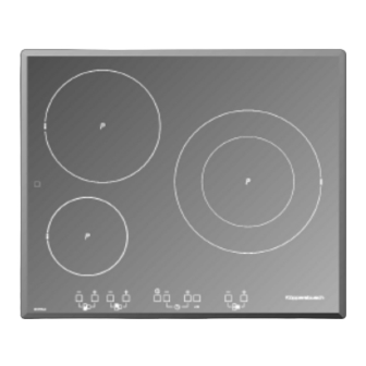
- Page 1 Induction hobs EKI 6130 / 6140 G1 Series Configuration and failure codes...
- Page 2 Service Manual: H1-53-01 Responsible: Dieter Rutz KÜPPERSBUSCH HAUSGERÄTE AG Email: dieter.rutz@kueppersbusch.de Tel.: (0209) 401-732 Customer Service Fax: (0209) 401-743 Postfach 100 132 Date: 25.08.2010 45801 Gelsenkirchen...
-
Page 3: Table Of Contents
Service Manual Contents Safety instructions ......................4 Repair instructions......................5 General information on induction ................. 5 Introduction........................5 User interface (USIF) ...................... 6 Performance of the user interface ................. 6 USIF different layouts.................... 6 Communication and connectors................... 7 System failures ....................... 8 Failure types...................... -
Page 4: Safety Instructions
Service Manual Safety instructions Danger! Repairs may only be carried out by a qualified electrician! Improper repairs can be extremely dangerous for the user. It is essential that you observe the following instructions in order to prevent electric shocks: • The casing and the frame may be live in the event of faults! Prior to repairs, disconnect the appliance from the mains! •... -
Page 5: Repair Instructions
Service Manual Repair instructions • Never attempt to carry out repairs by “randomly replacing” components! • Always proceed systematically and observe the technical documentation that goes with the appliance! • Electronic circuit boards are generally not repaired; instead they are completely replaced with original spare parts. -
Page 6: User Interface (Usif)
Service Manual User interface (USIF) Performance of the user interface The USIF is an infrared Touch Control system. It works at a nominal voltage of 230 VAC with a tolerance of +10% / - 15%. A brownout is defined as a condition where line voltage drops below 196 VAC for a duration less than or equal to 3 seconds nominally. -
Page 7: Communication And Connectors
Service Manual Option 5 • 3 induction zones with +/- keys on each zone (zone 1 is missing here), 2 digit timer with +/- keys, child-lock (led to indicate the lock state), IR port for configuration, buzzer Option 6 • 3 induction zones with +/- keys on each zone (zone 1 is missing here), no timer, child-lock (led to indicate the lock state), IR port for configuration, buzzer Communication and connectors... -
Page 8: System Failures
Service Manual System failures Failure types Regarding the system there are four types of failures depending on their gravity and the impact they may have on the behaviour of the appliance: 7.1.1 Failure type 1 These failures are the ones that affect only one cooking zone. The user may continue using the other cooking zones. - Page 9 Service Manual Every failure type 2 (that concerns one IPC only) is shown on the displays that are associated to that IPC. Every failure type 2 (that concerns one IPC only) is shown on the displays that are associated to that IPC.
-
Page 10: Failure Codes
Service Manual Failure codes Error codes are a precious aid to diagnostic. Take care to well identify the model to be troubleshooted, as codes do not always have the same meaning. In the following table there are gathered the codes and detailed descriptions, showed in the USIF, of the failures that could happen in the appliance from the IPC side. -
Page 11: Configuration And Test Mode
Service Manual Configuration and test mode Where the action on the board is not desired, the diagnostic will be limited to the defective element. Any action on the circuit shall be carried out after eliminating the causes that may be due to saucepans or to a bad installation. -
Page 12: Main Menu
Service Manual 5. If the process has been done correctly the decimal dot of zone 2 blinks for a few seconds, and the message “C O” is then showed on displays cooking zones 2 and 3. The system uses always displays cooking zones 2 and 3 to show information. - Page 13 Service Manual 9.2.2 Access to one of these modes Once the display is showing CO, CH or IF, to enter into one of these three modes it is necessary to press the CHILDLOCK key. As general performance CHILDLOCK key is a button that works as <enter>, confirming the current option.
- Page 14 Service Manual Once the right configuration number is chosen, then pressing CHILD LOCK it will be confirmed and downloaded inside the hob. The decimal dot of zone 2 blinks for a few seconds, while downloading. Finally the USIF goes, automatically, to checking mode. By using ON/STAND BY button the menu is left and the appliance will start its usual behaviour.
-
Page 15: Remarks For Service Activities
Service Manual Remarks for service activities In the following section are included some important remarks that shall be considered when changing some parts of the system. Next picture shows a general view of the induction module, together with the name given to each component. 10.1 General view of the induction module left fan... -
Page 16: Substitution Of The Touch Control
Service Manual 10.2 Substitution of the Touch Control When changing a defective TC for a new one, it should be taken special care on the right connection of the cables from IPCs to TC, as shown in the next picture. left TC connection right TC connection connected to IPC... -
Page 17: Substitution Of Ipc
Service Manual 10.3 Substitution of IPC 10.4 Types of IPCs (LS & SS) There are 2 different configurations for IPCs, depending on the so-called resonant capacitors (res caps). We call them configuration LS or SS. Configuration LS has different size of res caps pair. One pair is bigger than the other one. The bigger pair is intended to drive only a coil of diameter Ø... - Page 18 Service Manual 10.4.1 Position of IPCs inside the induction module A standard induction module includes 2 IPCs that can be placed in 2 different positions or addresses. Position A means address 1, and position B means address 2, as shown in figure “Configuration mode (CO)”...
-
Page 19: Substitution Of A Coil
Service Manual 10.5 Substitution of a coil 10.5.1 Coils There are 4 different coils, depending on their diameter: 145, 180, 210 and 260 mm. The last one is a dual coil (inner and outer), so it includes 4 wires for power supply, but only one wire for temperature sensor. -
Page 20: Wiring Diagrams
EKI 6140... - Page 23 EKI 6130...
Need help?
Do you have a question about the G1 Series and is the answer not in the manual?
Questions and answers