Johnson Controls LN Series Installation Instructions Manual
Hide thumbs
Also See for LN Series:
- Installation instructions manual (25 pages) ,
- Installation instructions manual (9 pages) ,
- Installation instructions manual (10 pages)
Advertisement
Quick Links
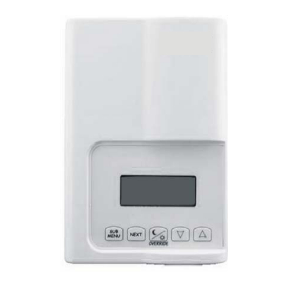
LN Series LN-VSTAT and LN-PSTAT Sensors
Installation Instructions
LN-VSTAT-1, LN-PSTAT-1
Applications
The LN Series LN-VSTAT and LN-PSTAT sensors are
specifically designed to connect to the SMRT ports of
the Johnson Controls' LN Series controllers. The
LN-VSTAT-1 works with the LN-VAVFLFS-1 and
LN-VVTLFS-1 controllers. The LN PSTAT-1 works with
the LN-PFCU-1 and LN-PFCUA-1 controllers. The
SMRT ports supply power and serial communications
to the LN-VSTAT and LN-PSTAT sensors. The device
provides precision local temperature sensing and it
allows occupants to adjust the local setpoint and view
the occupancy status, local space temperature, and
outside air temperature.
North American Emissions Compliance
United States
Compliance Statement (Part 15.19)
This device complies with Part 15 of the FCC Rules.
Operation is subject to the following two conditions:
1. This device may not cause harmful interference, and
2. This device must accept any interference received,
including interference that may cause undesired
operation.
Warning (Part 15.21)
Changes or modifications not expressly approved by the
party responsible for compliance could void the user's
authority to operate the equipment.
To comply with FCC RF exposure requirements for mobile
transmitting devices, this transmitter should only be used
or installed at locations where there is at least 20cm
separation distance between the antenna and all persons.
Canada
Industry Canada Statement
This Class (A) digital apparatus meets all the requirements
of the Canadian Interference-Causing Equipment
Regulations.
Le terme «IC» précédant le numéro de d'accréditation/
inscription signifie simplement que le produit est conforme
aux spécifications techniques d'Industry Canada.
Installation
For proper installation and subsequent operation of the
LN-VSTAT and LN-PSTAT sensors, follow these
recommendations:
•
Allow for proper clearance of device casing and
wiring terminals for easy access, hardware
configuration, and maintenance.
•
The sensor is designed to operate under the
following conditions:
•
•
•
Ensure proper ventilation of devices and avoid
areas where corroding, deteriorating, or explosive
vapors, fumes, or gasses may be present.
IMPORTANT: Work in a static-free area. Discharge
static electricity by touching a known, securely
grounded object. Do not handle the controller without
proper protection against static discharge. Use a wrist
strap when handling the controller. Secure the wrist
strap clamp to earth ground.
LN Series LN-VSTAT and LN-PSTAT Sensors Installation Instructions
Code No. LIT-12011302
Issued November 9, 2007
Supersedes May 2, 2007
Ambient temperature between 32º to 158ºF
(Oº to 70ºC)
Relative humidity from 0% to 95%,
non-condensing
1
Advertisement

Related Manuals for Johnson Controls LN Series


Summary of Contents for Johnson Controls LN Series
- Page 1 • Allow for proper clearance of device casing and wiring terminals for easy access, hardware The LN Series LN-VSTAT and LN-PSTAT sensors are configuration, and maintenance. specifically designed to connect to the SMRT ports of the Johnson Controls’ LN Series controllers. The •...
-
Page 2: Location Considerations
The LN-VSTAT and LN-PSTAT sensors should not be installed on an outside wall Note: The LN-VSTAT and LN-PSTAT sensors are not designed for outdoor use. • Install the sensor away from any heat source LN Series LN-VSTAT and LN-PSTAT Sensors Installation Instructions... - Page 3 8. Insert screws in mounting holes of the base. Do not overtighten the screws. Figure 3: LN-VSTAT and LN-PSTAT Sensors 9. Strip each wire 1/4 in. Security Screw 10. Gently push excess wiring back into the wall. LN Series LN-VSTAT and LN-PSTAT Sensors Installation Instructions...
- Page 4 Figure 4 shows the terminal wiring details.) on the bottom of the sensor to remove the cover. 1/8" Com. Jack Figure 4: LN-VSTAT and LN-PSTAT Sensors Terminal Wiring Details Figure 5: SMRT+ and SMRT- Output Terminal Location LN Series LN-VSTAT and LN-PSTAT Sensors Installation Instructions...
- Page 5 VAV LN-Sensor are wired to the SMRT+ and SMRT- controller and LN Sensor were first installed. terminals of the LN-Sensor (Figure 8). LN Series LN-VSTAT and LN-PSTAT Sensors Installation Instructions...
- Page 6 LN-VAV LN Sensor LN-VSTAT Figure 9: LN-VSTAT and LN-PSTAT sensors Wired to LN Sensor Using an Audio Plug Connect 1/8 in. Audio Plug from LN-VSTAT Sensor Figure 8: LN Sensor Wiring LN Series LN-VSTAT and LN-PSTAT Sensors Installation Instructions...
-
Page 7: Communications Wiring
LON network to controller. When you insert multiple wires into the avoid a short circuit. terminals, ensure you properly twist the wires together prior to inserting them into the terminal connectors. LN Series LN-VSTAT and LN-PSTAT Sensors Installation Instructions... - Page 8 The wiring scheme in figure is almost identical to a bus requires a free topology terminator. topology network, but since the stub length exceeds 3 meters, it becomes a free topology network which LN Series LN-VSTAT and LN-PSTAT Sensors Installation Instructions...
-
Page 9: Troubleshooting
Verify that the setpoint is configured correctly according to read properly the selected sensor model. Controls Group Metasys® is a registered trademark of Johnson Controls, Inc. 507 E. Michigan Street All other marks herein are the marks of their respective owners. Milwaukee, WI 53202 ©...
Need help?
Do you have a question about the LN Series and is the answer not in the manual?
Questions and answers