Interacoustics EyeSeeCam Instructions For Use Manual
Hide thumbs
Also See for EyeSeeCam:
- Instructions for use manual (589 pages) ,
- Instructions for use manual (407 pages)
Table of Contents
Advertisement
Quick Links
Advertisement
Table of Contents

Related Manuals for Interacoustics EyeSeeCam


Summary of Contents for Interacoustics EyeSeeCam
- Page 1 Science made smarter Instructions for Use – US vHIT EyeSeeCam...
-
Page 3: Table Of Contents
Servicing and maintenance ..................10 Software setup ......................10 3.5.1 Installing EyeSeeCam software ................. 10 3.5.2 Uninstalling the EyeSeeCam vHIT software - ........... 10 3.5.3 Starting EyeSeeCam from OtoAccess® 1.5 ............10 3.5.4 Starting EyeSeeCam from OtoAccess® 2.0 ............11 3.5.5... - Page 4 4.3.4 Edit and Default Calibrations ................19 Lateral impulses ......................20 4.4.1 Training guide ....................20 4.4.2 3D Head Modeling ..................... 21 4.4.3 Display laser during HIT..................22 4.4.4 Reject Noisy Eye Velocity .................. 23 4.4.5 Auto-Stop ......................23 4.4.6 Peak Head Velocity Limits .................
- Page 5 New Systems ......................55 Upgrade existing systems ..................55 Maintenance .......................... 57 General maintenance procedures ................57 How to clean Interacoustics Products ............... 57 Concerning repair ...................... 57 Warranty ........................58 Technical information ......................59 Appendix A: Electromagnetic compatibility (EMC) ............ 60...
-
Page 7: Introduction
Fax: +45 6371 3522 E-mail: info@interacoustics.com It is the purpose of this manual to provide users of the Interacoustics EyeSeeCam module with all the information required to carry out safe and reliable measurements. Dizziness is a frequent symptom in ENT, Neurology, and General Medicine. Part of the clinical examination of dizzy patients is based on the head impulse test (HIT) of the vestibulo-ocular reflex (VOR). -
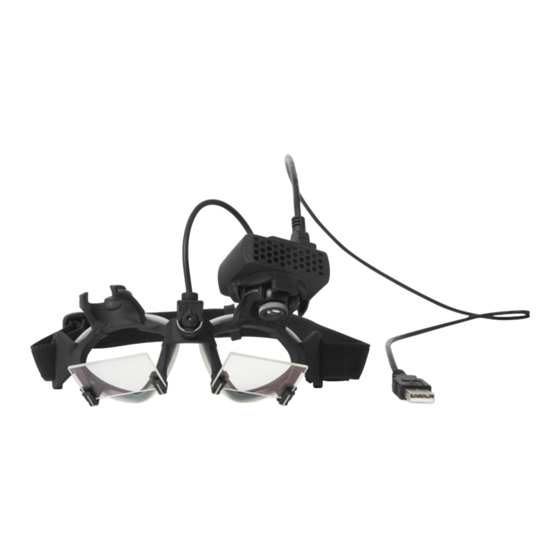
Page 8: Included Parts
The EyeSeeCam is intended for patient from 5 years and up. The patient must be physically sound as the procedures include some physical stimulation/movement. Patient must be able the see the target without the use of spectacles. Contra indications •... -
Page 9: About This Manual
Keep carton for future shipment The EyeSeeCam comes in its own shipping carton, which is specially designed for the EyeSeeCam. Please keep this carton. It will be needed if the instrument has to be returned for service. -
Page 10: Markings
Failing to do so may endanger the environment. The CE-mark indicates that Interacoustics A/S meets the requirements of Annex II of the Medical Device Directive 93/42/EEC. TÜV Product Service, Identification No. - Page 11 C). If this feels uncomfortable for the patient turn off the equipment for a while. The EyeSeeCam system must be serviced at least once a year. The service must include a • safety test. No parts can be serviced while in use with the patient.
- Page 12 D-0101516-E – 2019/03 EyeSeeCam vHIT - Instructions for Use - US Page...
-
Page 13: Getting Started And System Setup
Furthermore, Microsoft .Net 2.0 Framework and Windows Installer 3.x should be available. If these programs are not installed on your computer, you will be prompted to install them when running the EyeSeeCam installation. Just click yes when the installer asks you, and they will be installed automatically. -
Page 14: Windows Power Setting Setup
It is also necessary to disable Windows’ own power saving features: In control panel -> Power options properties, power manager, set power schemes to maximum performance as shown below: Figure 3.2.4-1 Power Option properties D-0101516-E – 2019/03 EyeSeeCam vHIT - Instructions for Use - US Page... -
Page 15: Usb Mode
USB mode The EyeSeeCam vHIT camera must only be connected to a USB 2.0 port. If the computer only has USB 3.0 ports the USB 3.0 controller must be disabled so that the ports will work in USB 2.0 mode. -
Page 16: Ir Illumination
IR illumination Light Emitting Diodes (LEDs) are positioned at the side of the camera objective lens. The lateral LEDs emit infrared light (IR). D-0101516-E – 2019/03 EyeSeeCam vHIT - Instructions for Use - US Page... -
Page 17: Focus Adjustment
5 laser dots are aligned horizontally and vertically. Do not adjust the calibration laser unduly. Adjust only if the dots have gone out of horizontal/vertical alignment. Figure 3.3.4-1 Calibration laser adjustment D-0101516-E – 2019/03 EyeSeeCam vHIT - Instructions for Use - US Page... -
Page 18: Servicing And Maintenance
The vHIT system must be serviced at least once a year. The service must include a safety test. Software setup Installation of OtoAccess® – Please refer to the OtoAccess® manual and documentation. Installation of EyeSeeCam vHIT software - Please refer to the EyeSeeCam installation CD and instruction. Installing EyeSeeCam software Follow the prompts on the screen to step through the software installation. -
Page 19: Starting Eyeseecam From Otoaccess® 2.0
Starting EyeSeeCam from OtoAccess® 2.0 Open OtoAccess® and select the tab for EyeSeeCam. Select the instrument module (in this example, EyeSeeCam) by clicking the EyeSeeCam icon in the upper left-hand corner. EyeSeeCam will open in a new window. Figure 3.5.4-1 OtoAccess® 2.0 Opening Screen Backing up files in OtoAccess®... - Page 20 D-0101516-E – 2019/03 EyeSeeCam vHIT - Instructions for Use - US Page...
-
Page 21: Test Procedures
Ask the participant if all five appearing laser points are clearly visible. If not, special lenses can be applied to the goggles for short sight correction. D-0101516-E – 2019/03 EyeSeeCam vHIT - Instructions for Use - US Page... -
Page 22: Adjust The Eye/Camera
From this starting position, the camera first needs to be rotated such that the pupil is centered horizontally. D-0101516-E – 2019/03 EyeSeeCam vHIT - Instructions for Use - US Page... -
Page 23: Calibrate The Patient
Figure 4.2.3-2 Calibration in progress screen. The big red dot in the Eye in Space plot (bottom right) indicates that the patient should fixate on the right calibration dot. D-0101516-E – 2019/03 EyeSeeCam vHIT - Instructions for Use - US Page... - Page 24 Evaluate the calibration: a successful calibration should form a cross with accumulations of gaze points around the instructed laser points. A false calibration shows scattered gaze points and has to be repeated. D-0101516-E – 2019/03 EyeSeeCam vHIT - Instructions for Use - US Page...
-
Page 25: Head Calibrations
100 deg/sec. The total duration of the head calibration is on the order of 15 sec. Start Head calibration Select Start to begin the test and select stop when finished. Figure 4.3.2-1 Diagram showing the different planes of head rotations. D-0101516-E – 2019/03 EyeSeeCam vHIT - Instructions for Use - US Page... -
Page 26: Calibration Report - Head
The three polar diagrams at the right of the report show the head movements from three different perspectives. D-0101516-E – 2019/03 EyeSeeCam vHIT - Instructions for Use - US Page... -
Page 27: Edit And Default Calibrations
Figure 4.3.4-1 Report function for calibration to allow default values or edit existing eye calibrations. You can edit the eye calibrations by clicking on one of the red dots and moving the dot to a new location. Figure 4.3.4-2 Edit eye calibrations D-0101516-E – 2019/03 EyeSeeCam vHIT - Instructions for Use - US Page... -
Page 28: Lateral Impulses
The most recent impulse is in a bolder black color. Figure 4.4.1-2 Legend for Head, Eye and History colors for impulses Figure 4.4.1-3 Legend for Head and Eye colors for real time data. D-0101516-E – 2019/03 EyeSeeCam vHIT - Instructions for Use - US Page... -
Page 29: Head Modeling
It can be used as a further guide to help you determine if the head is in the correct position and confirms which canals are being stimulated. Figure 4.4.2-1 Head and semicircular canal model D-0101516-E – 2019/03 EyeSeeCam vHIT - Instructions for Use - US Page... -
Page 30: Display Laser During Hit
For Suppression Head Impulses (SHIMP) the light will always be on. Figure 4.4.3-1 Display Laser during HIT menu D-0101516-E – 2019/03 EyeSeeCam vHIT - Instructions for Use - US Page... -
Page 31: Reject Noisy Eye Velocity
For the vertical impulses you will see the total eye movements (including torsion) and then next to those values you will see the component specific to vertical eye movements only. D-0101516-E – 2019/03 EyeSeeCam vHIT - Instructions for Use - US Page... -
Page 32: Set Normative Threshold Ranges
Gain Asymmetry in percentage. Each clinic should collect their own threshold levels and enter the values in the table. The values can be changed by clicking on the arrows keys after the numbers. Figure 4.4.7-2 Suggested threshold table D-0101516-E – 2019/03 EyeSeeCam vHIT - Instructions for Use - US Page... - Page 33 After entering new values or changing existing values, you will need to restart the program before the values can be updated. Figure 4.4.7-4 Restart EyeSeeCam to update threshold value changes Once you have entered values into the table then you will see shaded areas on your graphical displays.
-
Page 34: Default Settings
Before the default settings get reset you will get a pop-up message asking you to confirm the change. If you choose “Yes” to confirm the changes EyeSeeCam will quit and you will need to restart the program. Figure 4.4.8-2 Pop-up message to confirm reset to default settings D-0101516-E –... -
Page 35: Prepare To Test
Place both hands on the jaw of the patient from behind. The correct technique for positioning the hands during the impulses is shown below. Figure 4.4.9-2 Proper hand placements for impulses. D-0101516-E – 2019/03 EyeSeeCam vHIT - Instructions for Use - US Page... -
Page 36: Start Test
X’s. In the final report, the number of impulses will be the same as you see during the data collection unless there was artifact or noise present, and then the final algorithm will remove that tracing from the final report. D-0101516-E – 2019/03 EyeSeeCam vHIT - Instructions for Use - US Page... - Page 37 Figure 4.4.11-1 Data collection screen with Auto-Stop set to 7 D-0101516-E – 2019/03 EyeSeeCam vHIT - Instructions for Use - US Page...
-
Page 38: Vertical Impulses- Ralp/Larp
(RALP) or left downward to right-upward in the plane of the left anterior and right posterior canals (LARP). The EyeSeeCam protocol utilizes three well-documented properties of the VOR: 1) For fast head movements the axis of VOR eye rotation is head-fixed, i.e., independent of gaze direction, 2) the rotation axis can be separated into its horizontal, vertical, and torsional components, i.e., these components can... -
Page 39: Eye Orientation
Eye Orientation The correct eye orientation for the EyeSeeCam vertical canal testing protocol is straight-ahead along the midsagittal plane. This eye orientation ensures that the vertical pupil movement occurs within the calibrated range, where the measurement is optimal. -
Page 40: Head Orientation
For testing in the vertical planes you can select RALP and LARP protocols from the recording menu (right anterior/left posterior and left anterior/right posterior). Figure 4.5.3-2 Head impulse testing – vertical canals D-0101516-E – 2019/03 EyeSeeCam vHIT - Instructions for Use - US Page... -
Page 41: Prepare
The guide is there to show you if you are performing the impulses in the correct plane for that protocol. A line is plotted after each impulse that shows the angle measured for that thrust. Lines in the shaded area are within tolerance for an acceptable impulse angle. D-0101516-E – 2019/03 EyeSeeCam vHIT - Instructions for Use - US Page... -
Page 42: Start Test
After a reasonable number of impulses are collected in both planes (7-10 anterior and 7-10 posterior) you can hit Stop which will end the data collection. Or you can use the auto stop as described in section 4.4.5. D-0101516-E – 2019/03 EyeSeeCam vHIT - Instructions for Use - US Page... -
Page 43: Suppression Head Impulse Test (Shimp)
(driving the eyes in the opposite direction to the head movement) and then they will need to make a corrective saccade to come back to the target. Figure 4.6-2 SHIMP test on a normal subject shows gains of near 1.0 and large corrective saccades. D-0101516-E – 2019/03 EyeSeeCam vHIT - Instructions for Use - US Page... -
Page 44: Nystagmus Test
Figure 4.5.7-2 Nystagmus Measurement Screen D-0101516-E – 2019/03 EyeSeeCam vHIT - Instructions for Use - US Page... -
Page 45: Reports
If you hold down the control key you can click on multiple waveforms. After you have selected the waveforms that you want to delete, simply hit the delete key on the keyboard and these tracings will be removed from the analysis. D-0101516-E – 2019/03 EyeSeeCam vHIT - Instructions for Use - US Page... - Page 46 If you have deleted waveforms that you later decide you wanted to include in the analysis then you can use the Reset button in the bottom left-hand corner to reset the waveforms back to the original analysis. D-0101516-E – 2019/03 EyeSeeCam vHIT - Instructions for Use - US Page...
-
Page 47: Saccade Numerical Data Tables
Under the Data heading you will see individual saccade parameters including the peak, amplitude and latency for each saccade generated. Figure 5.1.2-2 Saccade Numerical Data Table D-0101516-E – 2019/03 EyeSeeCam vHIT - Instructions for Use - US Page... -
Page 48: Edit Saccades
You will see the latency and peak of each saccade. Figure 5.1.3-2 Saccade Editor D-0101516-E – 2019/03 EyeSeeCam vHIT - Instructions for Use - US Page... - Page 49 If you choose to delete a saccade simply right-click on the saccade you wish to remove and then click “Remove saccade”. This will unmark this saccade. Figure 5.1.3-3 Remove saccade by right-clicking Figure 5.1.3-4 The second saccade has been removed D-0101516-E – 2019/03 EyeSeeCam vHIT - Instructions for Use - US Page...
- Page 50 If you choose to change the start or ending point of the saccade simply click on one of the markers on the sides of the gray shading and drag the marker to its new location and drop there. Figure 5.1.3-6 Changing the start and stop time of the saccades. D-0101516-E – 2019/03 EyeSeeCam vHIT - Instructions for Use - US Page...
-
Page 51: Wave
Figure 5.1.4-1 Report menu item to select 3D waveform In this view you will see the saccades colored in orange. Figure 5.1.4-2 3D waveform view of impulse data D-0101516-E – 2019/03 EyeSeeCam vHIT - Instructions for Use - US Page... -
Page 52: Display
Stars represent right head impulses and diamonds represent left impulses. Figure 5.1.5-2 Monochrome symbols for left and right head impulses D-0101516-E – 2019/03 EyeSeeCam vHIT - Instructions for Use - US Page... -
Page 53: Maximum Time
The time scale can be extended from 300 – 700 ms by selecting Maximum time from the Report menu. Figure 5.1.6-1 Report menu for Maximum time scale This will allow you to view later overt saccades if they are present. D-0101516-E – 2019/03 EyeSeeCam vHIT - Instructions for Use - US Page... -
Page 54: Mirrored
If you choose to view your waveforms in the mirrored arrangements you can select Mirrored under the Report menu and this will invert the eye tracings so they overlap the head tracings Figure 5.1.7-1 Mirrored tracings D-0101516-E – 2019/03 EyeSeeCam vHIT - Instructions for Use - US Page... -
Page 55: Denoise
Denoise Denoise can only be applied to vertical impulses and it is used to remove artifact. Figure 5.1.8-1 Denoise option for vertical impulses D-0101516-E – 2019/03 EyeSeeCam vHIT - Instructions for Use - US Page... -
Page 56: Generate Reports
Figure 5.2.1-1 Full Report EyeSeeSix report Once Lateral, RALP and LARP tests are completed, an EyeSeeSix summary graph will automatically be generated. Figure 5.2.2-1 EyeSeeSix Report D-0101516-E – 2019/03 EyeSeeCam vHIT - Instructions for Use - US Page... - Page 57 Lateral gains are shown for both the 60 ms calculation and the average regression plot slope gain calculation. Vertical gains are shown as the average regression slope gain. D-0101516-E – 2019/03 EyeSeeCam vHIT - Instructions for Use - US Page...
- Page 58 This plot helps you verify that your vertical impulses were performed in the correct directions, indicating that you have stimulated the canal for which you had intended to measure the performance. D-0101516-E – 2019/03 EyeSeeCam vHIT - Instructions for Use - US Page...
-
Page 59: Printing Reports
Person ID. Print to external printer or PDF From the File menu, select Print Report. Figure 5.3.2-1 File menu option to Print Report You can also print to PDF. D-0101516-E – 2019/03 EyeSeeCam vHIT - Instructions for Use - US Page... -
Page 60: Export Completed Session Data
The file will be given a file name with “.zip” as the suffix and you will choose where you want the file to be saved on your computer. D-0101516-E – 2019/03 EyeSeeCam vHIT - Instructions for Use - US Page... -
Page 61: Video Recording
Select Test Sessions and Videos for Playback. The video files are saved in your videos files folder where they can be played back, renamed or exported. Figure 5.3.2-3 Previously Collected Videos D-0101516-E – 2019/03 EyeSeeCam vHIT - Instructions for Use - US Page... - Page 62 D-0101516-E – 2019/03 EyeSeeCam vHIT - Instructions for Use - US Page...
-
Page 63: Licensing
Once you have entered your license key, hit “Ok” and the software installation will start to run. If you hit cancel you can still use the software as a viewer for existing recordings. D-0101516-E – 2019/03 EyeSeeCam vHIT - Instructions for Use - US Page... - Page 64 Figure 5.3.2-5 Help menu Manage Licenses Here you can add the new camera license key and begin using that camera also. Figure 5.3.2-6 Help menu “add a new license key” D-0101516-E – 2019/03 EyeSeeCam vHIT - Instructions for Use - US Page...
-
Page 65: Maintenance
• solution Concerning repair Interacoustics is only considered to be responsible for the validity of the CE marking, effects on safety, reliability and performance of the equipment if: 1. Assembly operations, extensions, readjustments, modifications or repairs are carried out by authorised persons, 2. -
Page 66: Warranty
Accessories are free from defects in material and workmanship under normal use and service • for a period of ninety (90) days from the date of delivery by Interacoustics to the first purchaser If any product requires service during the applicable warranty period, the purchaser should communicate directly with the local Interacoustics service centre to determine the appropriate repair facility. -
Page 67: Technical Information
8 Technical information Medical CE-mark: The CE-mark indicates that Interacoustics A/S meets the requirements of Annex II of the Medical device Directive 93/42/EEC. Approval of the quality system is made by TÜV – Identification no. 0123 Standards: Safety: IEC 60601-1, Class II, Type B, applied parts... -
Page 68: Appendix A: Electromagnetic Compatibility (Emc)
NOTICE: There are no deviations from the collateral standard and allowances uses NOTICE: All necessary instruction for maintaining compliance with regard to EMC can be found in the general maintenance section in this instruction. No further steps required. D-0101516-E – 2019/03 EyeSeeCam vHIT - Instructions for Use - US Page... - Page 69 The EyeSeeCam has been tested for EMC emissions and immunity as a standalone EyeSeeCam. Do not use the EyeSeeCam adjacent to or stacked with other electronic equipment. If adjacent or stacked use is necessary, the user should verify normal operation in the configuration.
- Page 70 Note: UT is the A.C. mains voltage prior to application of the test level. Guidance and manufacturer’s declaration — electromagnetic immunity The EyeSeeCam is intended for use in the electromagnetic environment specified below. The customer or the user of the EyeSeeCam should assure that it is used in such an environment,...
- Page 71 Other : Date : Person : Please provide e-mail address or fax No. to whom Interacoustics may confirm reception of the returned goods: The above mentioned item is reported to be dangerous to patient or user In order to ensure instant and effective treatment of returned goods, it is important that this form is filled in and placed together with the item.
Need help?
Do you have a question about the EyeSeeCam and is the answer not in the manual?
Questions and answers