Sign In
Upload
Manuals
Brands
Juniper Manuals
Amplifier
PTX Series
Juniper PTX Series Inline Amplifier Manuals
Manuals and User Guides for Juniper PTX Series Inline Amplifier. We have
3
Juniper PTX Series Inline Amplifier manuals available for free PDF download: Hardware Manual, Quick Start
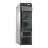
Juniper PTX Series Hardware Manual (320 pages)
Packet Transport Switch
Brand:
Juniper
| Category:
Switch
| Size: 9 MB
Table of Contents
Table of Contents
3
About the Documentation
21
Junos os Documentation and Release Notes
21
Objectives
21
Audience
22
Documentation Conventions
22
Table 1: Notice Icons
22
Table 2: Text and Syntax Conventions
22
Documentation Feedback
23
About the Documentation
23
Requesting Technical Support
24
Self-Help Online Tools and Resources
24
Opening a Case with JTAC
25
Chapter 1 PTX5000 Packet Transport Switch Overview
27
PTX5000 Packet Transport Switch Overview
29
PTX5000 Packet Transport Switch Description
29
Figure 1: Front View of the PTX5000 Packet Transport Switch
30
Figure 2: Rear View of the PTX5000 Packet Transport Switch
31
Chapter 3 PTX5000 Hardware Components Overview
27
Chapter 2 PTX5000 Packet Transport Switch System Architecture Overview
33
PTX5000 System Architecture Description
33
PTX5000 Packet Forwarding Engine Architecture
33
PTX5000 Hardware Components Overview
35
PTX5000 Hardware Component Overview
35
Table 3: PTX5000 Hardware Components
35
PTX5000 Component Redundancy
37
PTX5000 Chassis Description
38
Figure 3: Front View of PTX5000 Chassis
39
PTX5000 Midplane Description
40
Figure 4: Rear View of PTX5000 Chassis
40
PTX5000 Cable Management System
41
PTX5000 Centralized Clock Generator Overview
41
PTX5000 Centralized Clock Generator Description
42
CCG Slots
42
CCG Function
42
CCG Components
42
Figure 5: CCG
42
PTX5000 Centralized Clock Generator Leds
43
PTX5000 Cooling System Overview
43
Table 4: CCG Leds
43
Table 5: CCG Port Leds
43
PTX5000 Cooling System Description
44
Fan Trays
44
Figure 6: Vertical Fan Tray
44
Airflow
45
Figure 7: Horizontal Fan Tray
45
Air Filters
46
Figure 8: Airflow through the Chassis
46
Figure 9: Vertical Fan Tray Air Filter
46
Power Supply Cooling System
47
Figure 10: Horizontal Fan Tray Air Filter
47
Figure 11: PSM Door Air Filter
47
PTX5000 Control Board Overview
48
PTX5000 Control Board Description
48
Control Board Slots
48
Control Board Function
48
Control Board Components
48
Figure 12: Control Board
49
PTX5000 Control Board Leds
50
Figure 13: Control Board Leds
50
Table 6: Control Board Leds
50
PTX5000 Craft Interface Overview
51
Table 7: Control Board Port Leds
51
PTX5000 Craft Interface Description
52
Craft Interface Front Panel
52
Figure 14: Craft Interface
52
Craft Interface LCD
53
Figure 15: LCD in Idle Mode
53
LCD Navigation Buttons
54
PTX5000 Craft Interface Leds
54
Figure 16: LCD in Alarm Mode
54
Craft Interface Alarm Leds
55
Figure 17: Craft Interface Leds
55
Table 8: Alarm Leds on the PTX5000 Craft Interface
55
CCG Leds
56
Craft Interface Host Subsystem Leds
56
Craft Interface SIB Leds
56
Table 10: PTX5000 Host Subsystem Leds
56
Table 9: SIB Leds on the PTX5000 Craft Interface
56
Fan Trays Leds
57
Table 11: PTX5000 CCG Leds
57
Table 12: Power Supply Module Leds on the Craft Interface
57
Table 13: Fan Tray Leds on the Craft Interface
57
PTX5000 FPC Overview
58
PTX5000 FPC Description
58
FPC Slots
58
FPC Function
58
FPC Components
58
FPC Terminology
59
Identifying the Fpcs
59
Figure 18: FPC Edges
59
PTX5000 FPC Leds
60
Figure 19: FPC Supported by the Packet Transport Switch
60
Table 14: PTX5000 FPC Leds
60
PTX5000 Fpcs Supported
61
PTX5000 Host Subsystem Description
61
Table 15: Fpcs Supported by the PTX5000 Packet Transport Switch
61
PTX5000 PIC Overview
62
PTX Series PIC Description
62
PTX5000 Power System Overview
63
PTX5000 Power System Description
63
PTX5000 DC Power Distribution Unit
63
Figure 20: PIC
63
Figure 21: PDU
64
Table 16: Supported Power Distribution Units
64
PTX5000 DC Power Supply Module
65
Table 17: Supported Power Distribution Units
65
Figure 22: PSM
66
Table 18: Components Powered by each Zone
66
Table 19: Power Zone Fault Tolerance
67
PTX5000 Power Distribution Unit Leds
68
Figure 23: PDU
68
Table 20: Power Distribution Unit Leds
68
PTX5000 Power Supply Module Leds
69
Figure 24: PSM Leds
69
Table 21: Power Supply Module Leds
69
PTX5000 Routing Engine Overview
70
PTX5000 Routing Engine Description
70
Routing Engine Slots
70
Routing Engine Functions
70
Routing Engine Components
71
Routing Engine Boot Sequence
72
Figure 25: C2600 Routing Engine
72
PTX5000 Routing Engine Leds
73
Figure 26: Routing Engine Leds
73
Table 22: Routing Engine Leds
73
PTX5000 Switch Interface Board Overview
74
PTX5000 Switch Interface Board Description
74
SIB Slots
74
SIB Function
74
Supported Sibs
74
SIB Components
74
Figure 27: SIB
74
PTX5000 Switch Interface Board Leds
75
Figure 28: SIB
75
Table 23: SIB Leds
75
PTX5000 Packet Transport Switch Initial Installation
77
Chapter 5 Preparing for PTX5000 Packet Transport Switch Installation
77
Grounding the PTX5000 Packet Transport Switch
77
Installing the PTX5000 Packet Transport Switch Mounting Hardware
77
Chapter 4 PTX5000 Packet Transport Switch Installation Summary
79
Overview of Installing the PTX5000 Packet Transport Switch
79
Preparing for PTX5000 Packet Transport Switch Installation
81
Overview of Preparing the Site for the PTX5000 Packet Transport Switch
81
Rack Requirements for the PTX5000 Packet Transport Switch
82
Rack Size and Strength
82
Spacing of Mounting Bracket and Flange Holes
84
Connection to Building Structure
84
Figure 29: Typical Open-Frame Rack
84
PTX5000 Clearance Requirements for Airflow and Hardware Maintenance
85
Figure 30: Chassis Dimensions and Clearance Requirements
85
Unpacking the PTX5000 Packet Transport Switch
87
Chapter 6 Unpacking the PTX5000 Packet Transport Switch
87
Overview of Unpacking the PTX5000 Packet Transport Switch
87
Tools and Parts Required to Unpack the PTX5000 Packet Transport Switch
87
Unpacking the PTX5000 Packet Transport Switch
88
Figure 31: Contents of the Shipping Crate
89
Verifying the PTX5000 Packet Transport Switch Parts Received
89
Table 24: Packet Transport Switch Parts List
90
Table 25: Accessory Box Parts List
90
Chapter 7 Installing the PTX5000 Packet Transport Switch Mounting Hardware
93
Installing the PTX5000 Mounting Hardware for a Four-Post Rack or Cabinet
93
Installing Cage Nuts, if Needed
93
Table 26: Mounting Hole Locations for Installing the Four-Post Mounting Shelf and Rear-Support Bracket
93
Table 27: Mounting Hole Locations for Installing a PTX5000 Packet Transport Switch Chassis in a Four-Post Rack
94
Installing the Four-Post Mounting Shelf and Rear Support Bracket
95
Installing the PTX5000 Packet Transport Switch Mounting Hardware
95
Removing the Center-Mounting Brackets
96
Figure 32: Installing the Mounting Hardware for a Four-Post Rack
96
Installing the PTX5000 Mounting Hardware for an Open-Frame Rack
97
Installing Cage Nuts, if Needed
97
Figure 33: Center-Mounting Bracket Removal
97
Installing the Open-Frame Rack Mounting Shelf
99
Figure 34: Installing the Mounting Hardware for an Open-Frame Rack
99
Chapter 8 Installingtheptx5000Packettransportswitchusingamechanical
101
Lift
101
Overview of Installing a PTX5000 Packet Transport Switch Using a Mechanical
101
Installing the PTX5000 Packet Transport Switch Using a Mechanical
101
Mechanical Lift
102
Installing the PTX5000 Packet Transport Switch Using a Mechanical Lift
102
Figure 35: Loading the PTX5000 Onto the Lift
104
Figure 36: Installing the PTX5000 Packet Transport Switch in an Open-Frame
105
Figure 37: Installing the PTX5000 Packet Transport Switch in a Four-Post
106
Table 30: Mounting Hole Locations for Installing a Chassis in an Open-Frame
106
Table 31: Mounting Hole Locations for Installing a PTX5000 Packet Transport
107
Chapter 9 Grounding the PTX5000 Packet Transport Switch
109
Tools and Parts Required to Ground the PTX5000 Packet Transport Switch
109
Connecting the PTX5000 Grounding Cable
109
Figure 38: Connecting the Grounding Cable
110
Chapter 10 Connectingtheptx5000Packettransportswitchtoexternal
111
Devices
111
Tools and Parts Required to Connect the PTX5000 Packet Transport Switch to External Devices
111
Connecting the PTX5000 Packet Transport Switch to External
111
Connecting the PTX5000 Packet Transport Switch to a Management Console or Auxiliary Device
112
Figure 39: Connecting to the Console or Auxiliary Port on the Control Board
112
Connecting the PTX5000 Packet Transport Switch to a Management Console or
112
Auxiliary Device
112
Connecting the PTX5000 Packet Transport Switch to an External Alarm-Reporting Device
113
Connecting PIC Cables to the PTX5000 Packet Transport Switch
113
Device
113
Figure 40: Connecting PIC Cables
115
Device
116
Figure 41: Routing Engine Ethernet Cable Connector
116
Connecting the PTX5000 Packet Transport Switch to an External Clocking Device
117
Figure 42: Connecting to the Host/Ethernet Port on the Control Board
117
Chapter 11 Providing Power to the PTX5000 Packet Transport Switch
119
Switch
119
Connecting DC Power to the PTX5000 Packet Transport Switch
120
Figure 43: Removing the Input Power Tray
120
Figure 44: Connecting the DC Source Power Cable Lugs to an Input Power
121
Powering on the DC Powered PTX5000 Packet Transport Switch
122
Figure 45: Installing an Input Power Tray
122
Powering off the PTX5000 Packet Transport Switch
124
Chapter 12 Configuring the Junos os
127
Chapter 13 Switch
127
Preparing to Configure the Packet Transport Switch
127
Entering Configuration Mode
128
Configuring User Accounts and Passwords
128
Configuring System Attributes
128
Committing the Configuration
129
Performing the Initial Software Configuration for the PTX5000 Packet Transport
127
PTX5000 Maintenance, Troubleshooting, and Replacement Procedures
131
Maintaining Packet Transport Switch Hardware Components
133
Components
133
Routine Maintenance Procedures for the PTX5000 Packet Transport Switch
134
Maintaining the PTX5000 Centralized Clock Generators
134
Maintaining the PTX5000 Control Boards
135
Maintaining PTX5000 Cooling System Components
135
Maintaining the PTX5000 Air Filters
135
Maintaining the PTX5000 Fan Trays
136
Maintaining the PTX5000 Fpcs
137
Maintaining the PTX5000 Host Subsystem
137
Maintaining the PTX5000 Pics
138
Maintaining the PTX5000 PIC Cables
138
Maintaining the PTX5000 Power System
139
Maintaining the PTX5000 Routing Engines
140
Maintaining the PTX5000 Switch Interface Boards
140
Troubleshooting Packet Transport Switch Hardware Components
143
PTX5000 Troubleshooting Resources Overview
143
PTX5000 LED Overview
144
Craft Interface Leds
144
Component Leds
145
PTX5000 Alarm Messages Overview
145
Chassis Alarm Messages
146
Troubleshooting the PTX5000 Centralized Clock Generators
146
Table 32: Chassis Alarm Messages for the Ccgs
147
Troubleshooting the PTX5000 Cooling System
148
Troubleshooting the PTX5000 Fan Trays
148
Table 33: Fan Tray Alarms
148
Troubleshooting Temperature Alarms
151
Table 34: Temperature Alarms
151
Troubleshooting the PTX5000 Control Boards
161
Table 35: Chassis Alarm Messages for the Control Boards
161
Troubleshooting the PTX5000 Fpcs
162
Table 36: FPC Alarms
162
Troubleshooting the PTX5000 Host Subsystem
164
Table 37: Chassis Alarm Messages for Host Subsystems
164
Troubleshooting the PTX5000 Power System
165
Troubleshooting the PTX5000 Power Distribution Units
165
Table 38: Power Distribution Unit Alarms
165
Table 39: PDU Leds
166
Troubleshooting the PTX5000 Power Supply Modules
169
Table 40: PSM Chassis Alarms
169
Troubleshooting the PTX5000 Routing Engines
171
Troubleshooting the PTX5000 Pics and PIC Cables
173
Troubleshooting the PTX5000 Switch Interface Boards
174
Troubleshooting the PTX5000 Switch Fabric
177
Replacing Packet Transport Switch Hardware Components
181
PTX5000 Field-Replaceable Units
182
Tools and Parts Required for Replacing Hardware Components
182
Table 41: Field-Replaceable Units
182
Table 42: Tools and Parts Required for Component Replacement
183
Replacing a Centralized Clock Generator
184
Removing a Centralized Clock Generator
184
Installing a Centralized Clock Generator
185
Figure 46: Removing a CCG
185
Figure 47: Installing a CCG
185
Replacing a Cable between a PTX5000 CCG and an External Clocking
186
Device
186
Removing a Cable for an External Clocking Device from a PTX5000
186
Ccg
186
Installing a Cable between an External Clocking Device and a PTX5000
186
Replacing a PTX5000 Craft Interface
187
Removing a PTX5000 Craft Interface
187
Installing a PTX5000 Craft Interface
187
Figure 48: Removing the Craft Interface
187
Replacing a PTX5000 Control Board
188
Figure 49: Installing a Replacement Craft Interface
188
Removing a PTX5000 Control Board
189
Figure 50: Removing a Routing Engine from a Control Board
190
Figure 51: Removing a Control Board
190
Installing a PTX5000 Control Board
190
Figure 52: Installing a Control Board
191
Replacing a PTX5000 Horizontal Air Filter
192
Removing a PTX5000 Horizontal Air Filter
192
Figure 53: Installing a Routing Engine into a Control Board
192
Installing a PTX5000 Horizontal Air Filter
193
Figure 54: Horizontal Fan Tray Air Filter
193
Replacing a PTX5000 Vertical Air Filter
194
Removing a PTX5000 Vertical Air Filter
194
Figure 55: Vertical Fan Tray Air Filter
194
Installing a PTX5000 Vertical Air Filter
195
Replacing a PTX5000 Power Supply Module Air Filter
195
Removing an Air Filter
195
Installing the PTX5000 PSM Air Filter
196
Replacing a PTX5000 Management Console or Auxiliary Port Cable
196
Removing a Management Console or Auxiliary Port Cable
196
Figure 56: PSM Door Air Filter
196
Installing a Management Console or Auxiliary Port Cable
197
Replacing a PTX5000 Management Ethernet Cable
197
Removing a PTX5000 Management Ethernet Cable
197
Figure 57: Instaliing the Console or Auxiliary Port Cable
197
Installing a PTX5000 Management Ethernet Cable
198
Figure 58: Management Ethernet Cable Connector
198
Figure 59: Host/Ethernet Port on the Control Board
198
Replacing a PTX5000 FPC
199
Removing a PTX5000 FPC
199
Figure 60: Removing an FPC
201
Installing a PTX5000 FPC
201
Figure 61: Installing an FPC
202
Figure 62: Connecting Fiber-Optic Cable to a PIC
204
Removing a PTX5000 PIC
205
Installing a PTX5000 PIC
206
Replacing a PTX5000 PIC
204
Replacing a PTX5000 PIC Cable
207
Removing a PTX5000 PIC Cable
207
Installing a PTX5000 PIC Cable
208
Figure 63: Connecting Fiber-Optic Cable to a PIC
210
Figure 64: Small Form-Factor Pluggable (SFP)
211
Removing a PTX5000 PIC SFP+ Transceiver
211
Installing a PTX5000 PIC SFP+ Transceiver
212
Replacing a PTX5000 PIC SFP+ Transceiver
210
Replacing a PTX5000 PIC CFP Transceiver
213
Removing a PTX5000 PIC CFP Transceiver
213
Installing a PTX5000 PIC CFP Transceiver
214
Replacing a PTX5000 Horizontal Fan Tray
215
Removing a PTX5000 Horizontal Fan Tray
215
Installing a PTX5000 Horizontal Fan Tray
216
Figure 65: Removing an Upper Horizontal Fan Tray
216
Figure 66: Removing a Lower Horizontal Fan Tray
216
Replacing a PTX5000 Vertical Fan Tray
217
Figure 67: Installing an Upper Horizontal Fan Tray
217
Figure 68: Installing a Lower Horizontal Fan Tray
217
Removing a PTX5000 Vertical Fan Tray
218
Figure 69: Removing the Vertical Fan Tray
219
Installing a PTX5000 Vertical Fan Tray
219
Replacing a PTX5000 PDU
220
Removing a PTX5000 PDU
220
Figure 70: Installing a Vertical Fan Tray
220
Figure 71: Removing the Input Power Tray
221
Figure 72: Removing the PDU
222
Installing a PTX5000 PDU
223
Figure 73: Installing a PDU
223
Replacing a PTX5000 PDU DC Power Cable
224
Removing a PTX5000 PDU DC Power Cable
224
Figure 74: Installing an Input Power Tray
224
Figure 75: Removing the Input Power Tray
225
Figure 76: Disconnecting the DC Source Power Cable Lugs to an Input Power
225
Installing a PTX5000 PDU DC Power Cable
226
Replacing a PTX5000 PSM
227
Figure 77: Connecting the DC Source Power Cable Lugs to an Input Power Tray
227
Figure 78: Installing an Input Power Tray
227
Figure 79: Removing a PSM
228
Installing a PTX5000 PSM
228
Removing a PTX5000 PSM
228
Replacing a PTX5000 C2600 Routing Engine
229
Taking the PTX5000 Host Subsystem Offline
229
Removing a PTX5000 Routing Engine
231
Installing a PTX5000 Routing Engine
232
Figure 80: Removing a Routing Engine
232
Replacing a Compactflash Card in a PTX5000 Routing Engine
233
Removing a Compactflash Card from a PTX5000 Routing Engine
233
Figure 81: Installing a Routing Engine
233
Installing a Compactflash Card in a PTX5000 Routing Engine
234
Engine
235
Replacing a Solid-State Disk in a PTX5000 Routing Engine
235
Removing a Solid-State Disk from a PTX5000 Routing Engine
236
Installing a Solid-State Disk in a PTX5000 Routing Engine
237
Engine
237
Replacing a PTX5000 Switch Interface Board
238
Removing a PTX5000 Switch Interface Board
238
Installing a PTX5000 Switch Interface Board
239
Figure 82: Removing a SIB
239
Figure 83: Installing a SIB
240
Appendixes
241
Table 44: Packet Transport Switch Environmental Specifications
241
Appendix Aptx5000 Safety and Regulatory Compliance Information
243
Definition of Safety Warning Levels
243
General Safety Guidelines and Warnings
245
General Safety Guidelines for Juniper Networks Devices
245
General Safety Warnings for Juniper Networks Devices
246
Qualified Personnel Warning
246
Restricted Access Area Warning
246
Switch
248
Fire Safety Requirements for Juniper Networks Devices
249
Figure 84: ESD Points on the Packet Transport Switch
249
Figure 85: Placing a Component into an Electrostatic Bag
249
Fire Suppression
250
Fire Suppression Equipment
250
General Fire Safety Requirements
250
PTX5000 Installation Safety Guidelines
251
General Installation Safety Guidelines
251
Chassis Lifting Guidelines
251
Installation Safety Warnings for Juniper Networks Devices
252
Installation Instructions Warning
252
Rack-Mounting Requirements and Warnings
252
Ramp Warning
256
Laser and LED Safety Guidelines and Warnings
256
PTX5000 General Laser Safety Guidelines
257
Laser Safety Warnings for M Series, MX Series, and T Series Routers, and PTX Series Packet Transport Switches
257
Class 1 Laser Product Warning
257
Class 1 LED Product Warning
258
Laser Beam Warning
258
Radiation from Open Port Apertures Warning
259
Maintenance and Operational Safety Guidelines and Warnings
260
Devices
260
Battery Handling Warning
260
Jewelry Removal Warning
261
Lightning Activity Warning
262
Operating Temperature Warning
263
Product Disposal Warning
264
PTX5000 Electrical Safety Guidelines and Warnings
265
PTX5000 General Electrical Safety Guidelines
265
In Case of Electrical Accident
265
General Electrical Safety Guidelines
265
General Electrical Safety Warnings for Juniper Networks Devices
266
Grounded Equipment Warning
266
Grounding Requirements and Warning
267
Midplane Energy Hazard Warning
268
Multiple Power Supplies Disconnection Warning
268
Power Disconnection Warning
269
DC Power Electrical Safety Guidelines and Warnings
270
PTX5000 DC Power Electrical Safety Guidelines
270
Site Electrical Wiring Guidelines for Juniper Networks Devices
271
DC Power Electrical Safety Warnings for Juniper Networks Devices
272
Agency Approvals and Compliance Statements
275
PTX5000 Agency Approvals
275
PTX5000 Compliance Statements for NEBS
276
(Canada)
276
PTX5000 Compliance Statements for EMC Requirements
276
Community)
277
Compliance Statements for EMC Requirements for Juniper Networks Devices
277
Figure 86: Declaration of Conformity
278
(Japan)
279
Compliance Statements for EMC Requirements for Juniper Networks Devices (United States)
279
Compliance Statements for Environmental Requirements for Juniper Networks Devices
279
PTX5000 Compliance Statements for Acoustic Noise
279
Appendix B Packet Transport Switch Physical Specifications
281
PTX5000 Physical Specifications
281
Table 43: Physical Specifications
281
Table 43: Physical Specifications
282
Appendix C Packet Transport Switch Environmental Specifications
283
PTX5000 Packet Transport Switch Environmental Specifications
283
Table 44: Packet Transport Switch Environmental Specifications
283
Appendix D Power Guidelines, Requirements, and Specifications
285
PTX5000 Chassis Grounding Cable and Lug Specifications
285
Figure 87: Grounding Cable Lug
286
PTX5000 DC Power System Electrical Specifications
286
Table 45: Grounding Cable Specifications
286
Table 46: Power System Electrical Specifications
286
PTX5000 DC Power Distribution Unit Specifications
287
Table 47: PDU Electrical Specifications
287
PTX5000 DC Power Requirements
288
Table 48: Typical DC Power Requirements for Components
288
PTX5000 DC Power Cable and Lugs Specifications
289
DC Power Cables
289
Table 49: Power Cable Specifications
289
DC Power Lugs
290
Figure 88: DC Power Cable Lug
290
PTX5000 DC Power Distribution
290
Packet Transport Switch Cable, Wire, and Pinout Specifications and Guidelines
293
PTX5000 Network Cable Specifications and Guidelines
293
Network Cable and Transceiver Overview for PTX Series Packet Transport
293
Switches
293
Dispersion
294
Signal Loss in Multimode and Single-Mode Fiber-Optic Cable
294
Attenuation and Dispersion in Fiber-Optic Cable
294
Calculating Power Budget and Power Margin for Fiber-Optic Cables
295
Calculating Power Budget for Fiber-Optic Cable
295
Calculating Power Margin for Fiber-Optic Cable
295
Table 50: Estimated Values for Factors Causing Link Loss
296
PTX5000 Management Interface Cable Specifications
297
Table 51: Cable Specifications for Routing Engine Management
297
Port
298
RJ-45 Connector Pinouts for the PTX5000 AUXILIARY and CONSOLE Ports
298
Table 52: RJ-45 Connector Pinouts
298
PTX5000 Alarm Relay Contact Wire Specifications
299
Table 53: RJ-45 Connector Pinouts for the PTX5000 AUXILIARY and CONSOLE
299
Contacting Customer Support and Returning Packet Transport Switch
301
Hardware
301
Contacting Customer Support
301
Returning a Hardware Component to Juniper Networks, Inc
302
Tools and Parts Required to Remove Components from a PTX5000 Packet Transport Switch
303
Packing the PTX5000 Packet Transport Switch for Shipment
303
Packing the Packet Transport Switch Components for Shipment
304
Displaying PTX5000 Component Serial Numbers
304
PTX5000 Component Serial Number Locations
306
Horizontal Air Filter Serial Number Label
306
Figure 89: Serial Number ID Label
306
Chassis Serial Number Label
307
CCG Serial Number Label
307
Figure 90: Horizontal Air Filter Serial Number Label
307
Figure 91: Chassis Serial Number Label
307
Control Board Serial Number Label
308
Craft Interface Serial Number Label
308
Figure 92: CCG Serial Number Label
308
Figure 93: Control Board Serial Number Label
308
Figure 94: Craft Interface Serial Number Label
308
Horizontal Fan Tray Serial Number Label
309
Vertical Fan Tray Serial Number Label
309
Figure 95: Horizontal Fan Tray Serial Number Label
309
Figure 96: Vertical Fan Tray Serial Number Label
309
FPC Serial Number Label
310
PIC Serial Number Label
310
Figure 97: FPC Serial Number Label
310
Figure 98: 10-Gigabit Ethernet PIC Serial Number Label
311
Figure 99: 40-Gigabit Ethernet PIC Serial Number Label
311
PDU Serial Number Label
312
Figure 100: 100-Gigabit Ethernet PIC Serial Number Label
312
PSM Serial Number Label
313
Figure 101: PDU Serial Number Label
313
Figure 102: PSM Serial Number Label
313
Routing Engine Serial Number Label
314
SIB Serial Number Label
314
Figure 103: Routing Engine Serial Number Label
314
Figure 104: SIB Serial Number Label
314
Index
315
Index
317
Advertisement
Juniper PTX Series Quick Start (2 pages)
Packet Transport Router
Brand:
Juniper
| Category:
Network Router
| Size: 0 MB
Table of Contents
Part 1: Mount the PTX1000
1
Part 2: Connect Power to the PTX1000
1
Part 3: Perform the Initial Configuration
1
Safety Warnings Summary
2
Juniper PTX Series Quick Start (2 pages)
Optical Inline Amplifier
Brand:
Juniper
| Category:
Amplifier
| Size: 0 MB
Table of Contents
Part 1: Mount the Optical ILA
1
Part 2: Connect Power to the Optical ILA
1
Part 3: Perform the Initial Configuration
2
Safety Warnings Summary
2
Advertisement
Advertisement
Related Products
Juniper PTX10008
Juniper PTX10002-60C
Juniper PTX10003-80C
Juniper PTX1000
Juniper PTX10004
Juniper PTX10004-BASE3
Juniper PTX10016
Juniper PTX10002-36QDD
Juniper PTX10001-36MR
Juniper PTX10003-160C
Juniper Categories
Network Router
Switch
Gateway
Software
Network Hardware
More Juniper Manuals
Login
Sign In
OR
Sign in with Facebook
Sign in with Google
Upload manual
Upload from disk
Upload from URL