Datalogic SG4 Fieldbus Instruction Manual
Safety light curtains
Hide thumbs
Also See for SG4 Fieldbus:
- Instruction manual (136 pages) ,
- Quick manual (8 pages) ,
- Instruction manual (2 pages)
Table of Contents
Advertisement
Quick Links
Advertisement
Chapters
Table of Contents

Related Manuals for Datalogic SG4 Fieldbus


Summary of Contents for Datalogic SG4 Fieldbus
- Page 2 “SG4 FIELDBUS” Instruction Manual Ed.: 05/2018 © 2017 - 2018 Datalogic S.p.A. and/or its affiliates ALL RIGHTS RESERVED. Without limiting the rights under copyright, no part of this documentation may be reproduced, stored in or introduced into a retrieval system, or transmitted in any form or by any means, or for any purpose, without the express written permission of Datalogic S.p.A.
- Page 4 European directive. Since the directives and applicable standards are subject to continuous updates, and since Datalogic promptly adopts these updates, therefore the EU declaration of conformity is a living document. The EU declaration of conformity is available for competent authorities and customers through Datalogic commercial reference contacts.
-
Page 5: Table Of Contents
SG4 FIELDBUS TABLE OF CONTENTS GENERAL INFORMATION ..........................7 General description ............................7 Package contents ............................8 How to choose the device ..........................9 1.3.1 Detection capability ............................9 1.3.2 Height of the detection zone .......................... 10 1.3.3 Minimum installation distance ........................11 Typical applications ............................ - Page 6 SG4 FIELDBUS TECHNICAL DATA ............................50 10.1 Safety response time ............................. 51 10.1.1 Light curtain Detection time for Basic Models ....................51 10.1.2 Light curtain Detection time for Advanced Models ..................52 10.1.3 Data runtime on Bus (Light Curtain -> SafeLOGIC) ..................53 AVAILABLE MODELS ..........................
-
Page 7: General Information
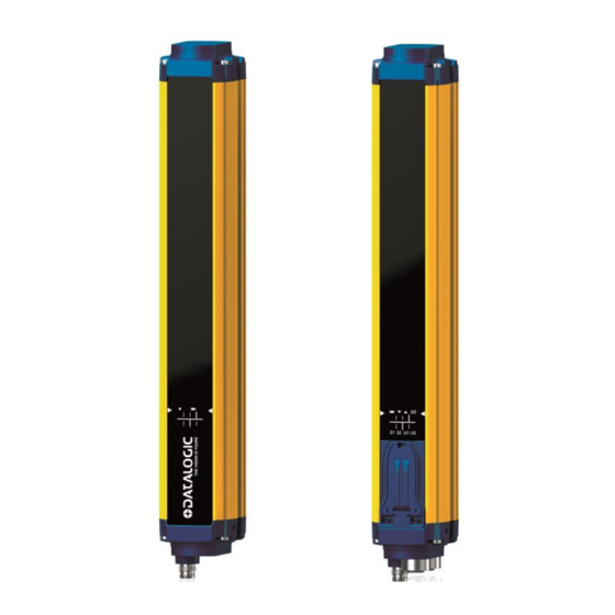
32). SG4 Fieldbus light curtains have no safety outputs (OSSDs). Instead they perform an otpical scan and send the result to a PLC via the Ethernet POWERLINK by means of the openSAFETY protocol. As soon as an object, or a limb or the operator’s body accidentally interrupts one or some of the infrared beams sent by the emitter, the... -
Page 8: Package Contents
As the required knowledge may not be completely included in this manual, we suggest the customer to contact Datalogic Technical Service for any necessary information relative to the functioning of the light curtains and the safety rules that regulate the correct installation (cfr. USER INTERFACE AND DIAGNOSTICS on page 46). -
Page 9: How To Choose The Device
SG4 FIELDBUS 1.3 HOW TO CHOOSE THE DEVICE There are at least three different main characteristics that should be considered when choosing a safety light curtain, after having evaluated the risk assessment. 1.3.1 Detection capability The detection capability (or resolution) of the device is the minimum diameter that an opaque object must have in order to obscure at least one of the beams that constitute the detection zone and to actuate the sensing device. -
Page 10: Height Of The Detection Zone
SG4 FIELDBUS 1.3.2 Height of the detection zone The controlled height is the height protected by the safety light curtain. Fig 2 - Detection Zone Models Controlled height Hp (mm) SG4-xx-015-OP-x SG4-xx-030-OP-x SG4-xx-045-OP-x SG4-xx-060-OP-x SG4-xx-075-OP-x SG4-xx-090-OP-x SG4-xx-105-OP-x 1050 SG4-xx-120-OP-x 1200... -
Page 11: Minimum Installation Distance
SG4 FIELDBUS 1.3.3 Minimum installation distance The safety device must be positioned at a specific safety distance (Fig 3 - on page 11). This distance must ensure that the dangerous area cannot be reached before the dangerous motion of the machine has been stopped by the Safety Control System. -
Page 12: Fig 4 - Installation Distance (Horizontal Positioning)
SG4 FIELDBUS When devices with > 40 mm resolution are used, the height of the top beam has to be ≥ 900 mm (H2) from machine supporting base while the height of the bottom beam has to be ≤ 300 mm (H1). -
Page 13: Typical Applications
With finger, hand and body protection, the SG4 FIELDBUS models can be implemented in any application where standard safety light curtains are currently used, in a wide range of applications where control and protection of the access to dangerous zones is necessary. -
Page 14: Fig 5 - Hazardous Point Protection On Automatic Machine
SG4 FIELDBUS Example 1: Hazardous point protection on a automatic machine The operator positions the part and takes it back after machining. The operator must be protected against possible abrasions while working. The operator positions the products and takes them back after working and must be protected against possible harm by movable parts of the machine. -
Page 15: Fig 6 - Fixed And Floating Blanking
SG4 FIELDBUS Example 2: Fixed and floating blanking The blanking function is used when an object detected in a defined part of the detection zone must not cause an OFF state of the light curtains outputs. Fixed blanking is when the object must remain in a fixed position, with a given tolerance. -
Page 16: Safety Information
SG4 FIELDBUS 1.5 SAFETY INFORMATION For a correct and safe use of the safety light curtains, the following points must be observed: The stopping system of the machine must be electrically controlled. This control system must be able to stop the dangerous movement of the machine within the total machine stopping time T as per paragraph Minimum installation distance on page 10 and during all working cycle phases. -
Page 17: Installation
The presence of intense electromagnetic disturbances could affect correct operation of the device.This condition shall be carefully assessed with the advice of DATALOGIC Technical Service. The operating distance of the device can be reduced in presence of smog, fog or airborne dust. -
Page 18: General Information On Device Positioning
SG4 FIELDBUS 2.2 GENERAL INFORMATION ON DEVICE POSITIONING The safety light curtain should be carefully positioned in order to provide the necessary protection. Access to the dangerous area must only be possible by passing through the protecting safety light beams. -
Page 19: Minimum Distance From Reflecting Surfaces
SG4 FIELDBUS 2.2.1 Minimum distance from reflecting surfaces Reflecting surfaces placed near the light beams of the safety device (over, under or laterally) can cause passive reflections. These reflections can affect the recognition of an object inside the controlled area. Moreover, if the RX receiver detects a secondary beam (reflected by the side-reflecting surface) the object might not be detected, even if the object interrupts the main beam. -
Page 20: Fig 12 - Minimum Distance From Reflective Surface
SG4 FIELDBUS for ESPE Type 4 EAA = 5° ( = ± 2.5°) Fig 12 - Minimum distance from reflective surface The formula to get Dsr is the following: For ESPE Type 4: Dsr (m) = 0.13 for operating distance < 3 m Dsr (m) = [0.5 x operating distance (m) x tan 5°]... -
Page 21: Distance Between Homologous Devices
SG4 FIELDBUS 2.2.2 Distance between homologous devices The following graphic shows the distance from the interfering devices (Ddo) according to the operating distance (Ddo) of the couple ( TXA – RXA ). If different safety devices have to be installed in adjacent areas, the emitter of one device must not interfere dangerously with the receiver of the other device. -
Page 22: Fig 15 - Recommended Positioning For Homologous Devices
SG4 FIELDBUS The following table shows, for convenience, the values of the minimum installation distances relative to some operating distances: Operating distance (m) Minimum installation distance (m) The interfering device (TXB) must be positioned at the same Ddo distance, calculated as shown above, even if closer to TXA respect to RXA. -
Page 23: Emitter And Receiver Orientation
SG4 FIELDBUS 2.2.3 Emitter and Receiver Orientation The two units shall be assembled parallel each other, with the beams arranged at right angles with the emission and receiving surface, and with the connectors pointing to the same direction. The configurations shown in the figure must be avoided:... -
Page 24: Use Of Deviating Mirrors
The alignment of the emitter and the receiver can be a very critical operation when deviating mirrors are used. Even very small displacements of the mirror is enough to lose alignment. The use of the DATALOGIC laser pointer accessory is recommended under these conditions. -
Page 25: Controls After First Installation
SG4 FIELDBUS 2.2.5 Controls after first installation The control operations to carry-out after the first installation and before machine start-up are listed hereinafter. The controls must be carried-out by qualified personnel, either directly or under the strict supervision of the person in charge of machinery Safety. -
Page 26: Mechanical Mounting
3 brackets, the third one as an additional support in the middle. 3.1 FIXING WITH “L” BRACKETS “L” metal brackets are included with all SG4 FIELDBUS models. They allow product installation where no alignment adjustment is needed. -
Page 27: Fixing With Optional Rotating Bracket Kit
SG4 FIELDBUS 3.2 FIXING WITH OPTIONAL ROTATING BRACKET KIT Rotating brackets available on request (4x KIT - Order Code 95ASE2840), can be used as an alternative or together with “L” brackets. Fig 21 - Rotating bracket assembly Fig 22 - Rotating bracket mounting options... -
Page 28: Anti-Vibration Supports
SG4 FIELDBUS 3.3 ANTI-VIBRATION SUPPORTS In case of applications with particularly strong vibrations, vibration dampers together with standard or rotating mounting brackets are recommended to reduce the impact of the vibrations (cfr.ACCESSORIES on page 57). Fig 23 - Anti-vibration supports with standard brackets... -
Page 29: Electrical Connections
SG4 FIELDBUS 4 ELECTRICAL CONNECTIONS 4.1 PIN-OUT AND CONFIGURATION PIN CONNECTION 4.1.1 Receiver (RX) Fig 24 - Receiver unit connectors placement For the receiver an M8 4-pin male connector is used for power supply, while two M12 D-coded female Ethernet connectors provides dual port Ethernet POWERLINK CN Node connection. -
Page 30: Emitter (Tx)
SG4 FIELDBUS POWERLINK (transmission technology, cable specification) Safety instrumented openSAFETY communication is embedded in the POWERLINK standard protocol and transmitted via the same network. S/UTP Cat5e must be used for transmission according to the 100Base-TX Fast Ethernet standard (overall shield with 2 x 2 twisted pair unshielded copper wires). -
Page 31: Notes On Connections
SG4 FIELDBUS 4.2 NOTES ON CONNECTIONS For the correct operation of the safety light curtains, the following precautions regarding the electrical connections have to be respected: Do not place connection cables in contact with or near high-voltage cables and/or cable undergoing high current variations (e.g. -
Page 32: Alignment Procedure
SG4 FIELDBUS 5 ALIGNMENT PROCEDURE The alignment between the emitting and the receiving units is necessary to obtain the correct operation of the light curtain. A good alignment prevents outputs instability caused by dust or vibrations. The alignment is perfect if the optical axes of the first and the last emitting unit's beams coincide with the optical axes of the corresponding elements of the receiving unit. -
Page 33: Fig 27 - Led User Interface Label
SG4 FIELDBUS A LED user Interface provides indications about optic alignment toghether with Fieldbus connection status. LEDs are clearly identified through symbols or labels allowing their immediate reading, independently of bars directions; Find below a short description of Leds indications about optical alignment. -
Page 34: Correct Alignment Procedure
SG4 FIELDBUS 5.1 CORRECT ALIGNMENT PROCEDURE The light curtain alignment can be effected only after having completed the mechanical installation and the electrical connections as described above. Compare alignment results with those given in the following table: Check the green LED ( ) and the yellow LED ( ) on the TX unit. -
Page 35: Commissioning And Configuration
The SG4 Filedbus uses the B&R Automation Studio environment for integration with the PLC through Description Files. The SafeDESIGNER configuration tool provides the configuration and programming interface for the safety application. Depending on the SG4 Fieldbus model the following hardware and software requirements apply: Model Automation Studio 4.2.8.x... -
Page 36: Device Description File
1. Select Tools -> Import Fieldbus Device Fig 28 - Step 1 - Importing the device For SG4 FIELDBUS Series light curtains different description files are available depending on the specific light curtain model, please refer to the table below:... -
Page 37: Fig 29 - Step 2 - Importing The Device
SG4 FIELDBUS 2. Select first the file with extension .xosdd related to the device you want to import. Fig 29 - Step 2 - Importing the device 3. Select the file with extension .xdd according to the one selected above. -
Page 38: Fig 31 - Sg4 Fieldbus Devices In Automation Studio Hardware Catalog
SG4 FIELDBUS Once imported, the device will be present in Automation Studio Hardware Catalog, ready to be used in the project. Just search for the right device and drag&drop. Fig 31 - SG4 FIELDBUS devices in Automation Studio Hardware Catalog 38/75... -
Page 39: Safety Firmware Update
SG4 FIELDBUS 6.5 SAFETY FIRMWARE UPDATE When importing Device Description Files (.XDD/.XOSDD) make sure in same folder there also is one .fw file. Fig 32 - Description Files packet including firmware This is the Light Curtain Safety Firmware that will be embedded in PLC project and automatically loaded on the device when first connected on Ethernet POWERLINK bus. -
Page 40: Setting Device Address
SG4 FIELDBUS 6.6 SETTING DEVICE ADDRESS In Automation Studio right-click on SG4 FIELDBUS device and select “Change node number”, set the address from 1 to 240. Fig 34 - Select EPL device address in Automation Studio On device choose same address by setting the two rotary switches under the blue plastic flap. -
Page 41: Configuring A Light Curtain In Safedesigner
SG4 FIELDBUS 6.7 CONFIGURING A LIGHT CURTAIN IN SAFEDESIGNER To configure the device accordingly with its resolution, height and typology, open SafeDEISGNER (right-click on the SafeLOGIC and select SafeDESIGNER) Fig 36 - open SafeDESIGNER Change the LC parameters according with the specific light curtain model. For example, for 14mm models with 150... -
Page 42: Process Data Structure
SG4 FIELDBUS 6.8 PROCESS DATA STRUCTURE 6.8.1 Control Byte Control byte represents a set of information transmitted from the PLC to the light curtain. The table below shows in details the meaning of the single bits. Name Function Acknowledge The control bit "Reset" is used to acknowledge an error state or... -
Page 43: Status Byte
SG4 FIELDBUS 6.8.2 Status byte Control byte represents a set of information transmitted from the light curtain to the PLC. The table below shows in details the meaning of the single bits. Name Function Functioning Status of light curtain and connection: when 0 all other bits are non-significant. -
Page 44: Single Beam Transport Set (Advanced Light Curtain Only)
6.8.3 Single beam transport set (Advanced Light Curtain only) SG4 FIELDBUS Advanced Light Curtains implements openSAFETY Vision profile, which one of the key functionalities is the ability to transport single beams information for further analysis and advanced functions in combination with dedicated safety code of functional blocks library. -
Page 45: Safedesigner Configuration For Advanced Models
SG4 FIELDBUS 6.9 SAFEDESIGNER CONFIGURATION FOR ADVANCED MODELS From SafeDesigner 4.3.3, LightCurtain_SF library provides a set of functional blocks (FUBs) which allow safety light curtain advanced functions, taking advantage of single beam information transport. To add the library to the current project choose Add Library from the Project menu in SafeDESIGNER. -
Page 46: User Interface And Diagnostics
SG4 FIELDBUS 7 USER INTERFACE AND DIAGNOSTICS 7.1 USER INTERFACE Fig 44 - Receiver Fig 45 - Emitter On the bottom side of the light curtain a user interface with 8 LEDs helps the customer to check the status of the light curtain and the POWERLINK / openSAFETY variation. -
Page 47: Periodical Checks
SG4 FIELDBUS 8 PERIODICAL CHECKS The following is a list of recommended check and maintenance operations that should be periodically carried-out by qualified personnel (cfr. Controls after first installation on page 24) Check that: The ESPE stays locked ( red) during beam interruption along the entire protected area, using the suitable “Test Piece”... -
Page 48: General Information And Useful Data
The safety devices fulfill their safety function only if they are correctly installed, in accordance with the Standards in force. If you are not certain to have the expertise necessary to install the device in the correct way, DATALOGIC is at your disposal to assist you during the installation. -
Page 49: Device Maintenance
Please do not use on plastic surfaces or on light curtain painted surfaces: alcohol or solvents wool or synthetic cloths paper or other abrasive materials 9.1 PRODUCT DISPOSAL DATALOGIC recommends to dispose of the product in compliance with local laws or contact authorised waste collection centres. 49/75... -
Page 50: Technical Data
SG4 FIELDBUS 10 TECHNICAL DATA SAFETY CATEGORY Type 4 (rif. EN 61496-1: 2013) SIL 3 (rif. EN 61508) SIL CL 3 (ref. EN 62061:2005/A2: 2015) PL e, Cat. 4 (rif. EN ISO 13849-1: 2015) PFHd [1/h] = 1,02E-08 MTTFd [years] = 118... -
Page 51: Safety Response Time
SG4 FIELDBUS 10.1 SAFETY RESPONSE TIME Since SG4 FIELDBUS has no safety outputs it’s not possible to define a worst case Response Time from detection to output deactivation only depending on light curtain. Total Safety Response Time will depend on Light Curtain detection time, Data Runtime on the bus, output activation and actuator stopping time. -
Page 52: Light Curtain Detection Time For Advanced Models
SG4 FIELDBUS 10.1.2 Light curtain Detection time for Advanced Models Model Time (ms) Tcycle SG4-14-015-OP-A SG4-14-030-OP-A SG4-14-045-OP-A SG4-14-060-OP-A SG4-14-075-OP-A SG4-14-090-OP-A SG4-14-105-OP-A SG4-14-120-OP-A SG4-14-135-OP-A SG4-14-150-OP-A SG4-14-165-OP-A SG4-14-180-OP-A SG4-30-015-OP-A SG4-30-030-OP-A SG4-30-045-OP-A SG4-30-060-OP-A SG4-30-075-OP-A SG4-30-090-OP-A SG4-30-105-OP-A SG4-30-120-OP-A SG4-30-135-OP-A SG4-30-150-OP-A SG4-30-165-OP-A SG4-30-180-OP-A Please note that Detection Times from table above are only valid when using S_ESPE_Out of any any function block from LightCurtain_SF Library with S_CycleFilter input set to 0. -
Page 53: Data Runtime On Bus (Light Curtain -> Safelogic)
Default Safe Data Duration x (Default Additional Tolerated Packet Loss + 1) Case 2) "Manual Configuration" for SG4 FIELDBUS node is set to YES: Safe Data Duration and Additional Tolerated Packet Loss from particular SG4 FIELDBUS node has to be used in formula below. -
Page 54: Available Models
SG4 FIELDBUS 11 AVAILABLE MODELS Number Resolution Protected Base Model Advanced Model (mm) Height Beams SG4-14-015-OP-B 957901770 SG4-14-015-OP-A 957902050 SG4-14-030-OP-B 957901780 SG4-14-030-OP-A 957902060 SG4-14-045-OP-B 957901790 SG4-14-045-OP-A 957902070 SG4-14-060-OP-B 957901800 SG4-14-060-OP-A 957902080 14 mm SG4-14-075-OP-B 957901810 SG4-14-075-OP-A 957902090 FINGER SG4-14-090-OP-B 957901820... -
Page 55: Overall Dimensions
SG4 FIELDBUS 12 OVERALL DIMENSIONS Fig 49 - Overall dimensions (mm) MODELS Ltot (mm) L controlled height (mm) SG4-xx-015-OP-x 233,6 SG4-xx-030-OP-x 383,3 SG4-xx-045-OP-x SG4-xx-060-OP-x 682,7 SG4-xx-075-OP-x 832,4 SG4-xx-090-OP-x 982,1 SG4-xx-105-OP-x 1131,8 1050 SG4-xx-120-OP-x 1281,5 1200 SG4-xx-135-OP-x 1431,2 1350 SG4-xx-150-OP-x 1580,9... -
Page 56: Included Accessories
SG4 FIELDBUS 13 INCLUDED ACCESSORIES Metal angled fixing bracket (ST-KSTD) MODEL DESCRIPTION ST-KSTD Angled fixing bracket (4 pcs kit) Fig 50 - Dimensions (mm) 56/75... -
Page 57: Accessories
SG4 FIELDBUS 14 ACCESSORIES (dimensions in mm) 14.1 (ST-KSTD) METAL ANGLED FIXING BRACKET MODEL DESCRIPTION CODE ST-KSTD Angled fixing bracket (4 pcs kit) 95ACC1670 Fig 51 - ST-KSTD 57/75... -
Page 58: Fig 52 - Angled Fixing Bracket
SG4 FIELDBUS Angled fixing bracket mounting with orientable and antivibration supports MODEL DESCRIPTION CODE ST-K4OR Orientable supports (4 pcs kit) 95ACC1680 ST-K6OR Orientable supports (6 pcs kit) 95ACC1690 ST-K4AV Antivibration supports (4 pcs kit) 95ACC1700 ST-K6AV Antivibration supports (6 pcs kit) -
Page 59: St-Kpxmp) Plastic Angled Fixing Bracket
SG4 FIELDBUS 14.2 (ST-KPXMP) PLASTIC ANGLED FIXING BRACKET MODEL DESCRIPTION CODE ST-KP4MP Angled fixing bracket (4 pcs kit) 95ASE1100 ST-KP6MP Angled fixing bracket (6 pcs kit) 95ASE1110 Fig 56 - ST-KPxMP 59/75... -
Page 60: Fig 57 - Angled Fixing Bracket
SG4 FIELDBUS Angled fixing bracket mounting with orientable and antivibration supports MODEL DESCRIPTION CODE ST-K4OR Orientable supports (4 pcs kit) 95ACC1680 ST-K6OR Orientable supports (6 pcs kit) 95ACC1690 ST-K4AV Antivibration supports (4 pcs kit) 95ACC1700 ST-K6AV Antivibration supports (6 pcs kit) -
Page 61: St-K4Rot-Op) Metal Rotating Fixing Bracket
SG4 FIELDBUS 14.3 (ST-K4ROT-OP) METAL ROTATING FIXING BRACKET MODEL DESCRIPTION CODE ST-K4ROT-OP Rotating fixing bracket (4 pcs kit) 95ASE2840 Fig 61 - Dimensions (mm) 61/75... -
Page 62: Sg-Psm) Protective Stands With Adjustable Mirrors
SG4 FIELDBUS 14.4 (SG-PSM) PROTECTIVE STANDS WITH ADJUSTABLE MIRRORS MODEL DESCRIPTION CODE SG-PSM-2-500 Protective stand with 2 mirrors H=500 mm 95ASE2300 SG-PSM-3-800 Protective stand with 3 mirrors H=800 mm 95ASE2310 SG-PSM-4-900 Protective stand with 4 mirrors H=900 mm 95ASE2320 SG-PSM-4-1200... -
Page 63: Sg-Psb) Protective Stands
SG4 FIELDBUS 14.5 (SG-PSB) PROTECTIVE STANDS MODEL DESCRIPTION L (mm) CODE SG-PSB 600 Protective stand H=600 mm 95ASE2240 SG-PSB 1000 Protective stand H=1000 mm 1000 95ASE2250 SG-PSB 1200 Protective stand H=1200 mm 1200 95ASE2260 SG-PSB 1650 Protective stand H=1650 mm... -
Page 64: Sg-P) Plate Kit For Protective Stands
SG4 FIELDBUS 14.6 (SG-P) PLATE KIT FOR PROTECTIVE STANDS MODEL DESCRIPTION CODE SG-P Plate kit with springs 95ASE2290 Fig 68 - Dimensions (mm) Mounting with SG-PSB Fig 69 - Mounting 64/75... -
Page 65: Se-S) Columns And Floor Stands
SG4 FIELDBUS 14.7 (SE-S) COLUMNS AND FLOOR STANDS MODEL DESCRIPTION L(mm) X (mm) CODE SE-S 800 Column and floor stand H= 800 mm 30x30 95ACC1730 SE-S 1000 Column and floor stand H= 1000 mm 1000 30x30 95ACC1740 SE-S 1200 Column and floor stand H= 1200 mm... -
Page 66: Sg-Dm) Deviating Mirrors
SG4 FIELDBUS 14.8 (SG-DM) DEVIATING MIRRORS MODEL DESCRIPTION L1 (mm) L2 (mm) L3 (mm) CODE SG-DM 600 Deviating mirror version 600 mm 95ASE1680 SG-DM 900 Deviating mirror version 900 mm 95ASE1690 SG-DM 1200 Deviating mirror version 1200 mm 1145 1180... -
Page 67: Fig 73 - Mounting Kit
SG4 FIELDBUS Mounting kit for SG-DM with SE-S column and floor stands MODEL DESCRIPTION CODE ST-DM SG-DM mounting kit (2 pcs kit) 95ASE1940 Fig 73 - Mounting kit For each SG-DM mirror order 1 mounting kit ST-DM. Mounting kit SG-DM on SG-PSB (ST-PS-DM) -
Page 68: Sg-Ls) Pmma Lens Shield
SG4 FIELDBUS 14.9 (SG-LS) PMMA LENS SHIELD MODEL DESCRIPTION CODE SG-LS 150 Lens shield H=150 mm (5 pcs) 95ASE1450 SG-LS 300 Lens shield H=300 mm (5 pcs) 95ASE1460 SG-LS 450 Lens shield H=450 mm (5 pcs) 95ASE1460 SG-LS 600 Lens shield H=600 mm (5 pcs) -
Page 69: Tp) Test Piece
SG4 FIELDBUS 14.10 (TP) TEST PIECE MODEL DESCRIPTION CODE TP-14 Test piece Ø 14mm L=300mm 95ACC1630 TP-30 Test piece Ø 30mm L=300mm 95ACC1650 TP-40 Test piece Ø 40mm L=300mm 95ACC1820 14.11 CONNECTION CABLES 4-pole M8 cables MODEL DESCRIPTION CODE CS-B1-02-G-03... -
Page 70: Sg-Lp) Laser Pointer
SG4 FIELDBUS 14.13 (SG-LP) LASER POINTER MODEL DESCRIPTION CODE SG-LP Laser pointer 95ASE5590 The laser pointer of the SG-LP series represents a valid alignment and installation support for the safety light curtain series. The pointer can be moved along the light curtain profile to verify the complete device alignment (top and bottom). -
Page 71: Glossary
SG4 FIELDBUS 15 GLOSSARY AOPD (Active optoelectronic protective device): its detection function is achieved thanks to the use of optoelectronic receivers and emitters detecting the optical beams interruptions inside the device caused by an opaque object present inside the specified detecting area. - Page 72 SG4 FIELDBUS MPCE (Machine primary control element): electrically-powered element having the direct control of machine regular operation so as to be the last element, in order of time, to operate when the machine has to be enabled or blocked. N.C.: normally closed N.O.: normally opened...
- Page 73 Fig 46 - Total Safety Response time .......................... 51 Fig 47 - SafeDESIGNER response time parameters for main SafeLOGIC..............53 Fig 48 - SafeDESIGNER response time parameters for generic SG4 FIELDBUS node ........... 53 Fig 49 - Overall dimensions (mm) ..........................55 Fig 50 - Dimensions (mm) ............................
- Page 74 SG4 FIELDBUS Fig 60 - Angled fixing bracket + Orientable support + Antivibration support .............. 60 Fig 61 - Dimensions (mm) ............................61 Fig 62 - Protective stands with adjustable mirrors SG-PSM ..................62 Fig 63 - Protective stands with adjustable mirrors SG-PSM ..................62 Fig 64 - Protective stands with adjustable mirrors SG-PSM ..................
- Page 75 SG4 FIELDBUS 75/75...
Need help?
Do you have a question about the SG4 Fieldbus and is the answer not in the manual?
Questions and answers