Datalogic SG4 FIELDBUS Series Quick Manual
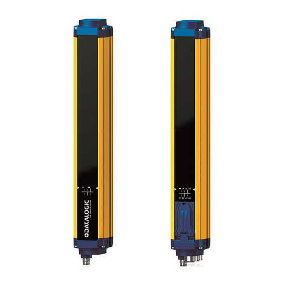
Safety light curtains with infrared beams
Hide thumbs
Also See for SG4 FIELDBUS Series:
- Instruction manual (136 pages) ,
- Instruction manual (75 pages) ,
- Instruction manual (73 pages)
Advertisement
This Quick Reference Guide does not replace the Instruction Manual. Download
the Instruction Manual by reading the QR code here or at: www.datalogic.com.
Click on Support > Search by product and enter the SG4 family name, then
select your product from the dropdown list. Click on the Manuals & Technical
Literature link to download your Instruction Manual. The Instruction Manual must
be available at all times when installing and working with the product.
The following points must be observed for a correct and safe use of the safety light curtains of the SG4
FIELDBUS series:
The stopping system of the machine must be electrically controlled.
This control system must be able to stop the dangerous movement of the machine within the total machine stopping
time T as per cfr. 1.3 of the Instruction Manual and during all working cycle phases.
Mounting and connection of the safety light curtain must be carried out only by qualified personnel, according to the
indications included in the special sections (refer to cfr. 2; 3; 4; 5) and in respect to the applicable Standards.
The safety light curtain must be securely installed so that access to the dangerous zone is not possible without
interrupting the beams.
The personnel operating in the dangerous area must be well-trained and must have adequate knowledge of all the
operating procedures of the safety light curtain.
Please carefully read the instructions for the correct functioning before powering the light curtain.
Precautions to be observed for the choice and installation of the device
Make sure that the protection level assured by the SG4 device (Type 4) is compatible with the real danger
level of the machine to be controlled, according to EN ISO 13849-1 and EN 62061.
The dimension of the smallest object to be detected must be larger than the resolution level of the device.
The ESPE must be installed in a room complying with the technical characteristics indicated in cfr. "Technical data" of
the Instruction Manual.
Do not place the device near intense and/or flashing light sources and, in particular, close to receiving unit front surface.
The presence of intense electromagnetic disturbances could jeopardise device operation. This condition has to carefully
evaluated with the support of the Datalogic Technical service.
The operating distance of the device can be reduced in presence of smog, fog or airborne dust.
A sudden change in environment temperature, with very low minimum peaks, can generate a small condensation layer
on the lenses and so jeopardise functioning.
Reflecting surfaces near the safety light curtain light beam (above, under or lateral) can cause passive reflections that
can jeopardise functioning.
The safety device must be installed at a distance which is major or equal to the minimum safety distance S to ensure
that the operator can not reach the dangerous area until the moving dangerous object has been blocked by the ESPE.
The failure to respect the safety distance reduces or cancels ESPE the protection function. For more detailed
information about calculation of safety distance, please refer to the Instruction Manual.
SG4 FIELDBUS
Safety light curtains with infrared beams
SAFETY INFORMATION
1
(SG4-xx-xxx-OP-x)
QUICK GUIDE
Advertisement
Table of Contents

Related Manuals for Datalogic SG4 FIELDBUS Series


Summary of Contents for Datalogic SG4 FIELDBUS Series
- Page 1 QUICK GUIDE This Quick Reference Guide does not replace the Instruction Manual. Download the Instruction Manual by reading the QR code here or at: www.datalogic.com. Click on Support > Search by product and enter the SG4 family name, then select your product from the dropdown list. Click on the Manuals & Technical Literature link to download your Instruction Manual.
-
Page 2: Pin-Out And Configuration Pin Connection
PIN-OUT AND CONFIGURATION PIN CONNECTION Receiver (RX) Emitter (TX) For the receiver an M8 4-pin male connector is used for power supply, while two M12 D-coded female Ethernet connectors provide dual port Ethernet Powerlink CN Node connection. SIGNAL POWER CONNECTOR 24VDC (BROWN) NOT USED (WHITE) 0 VDC (BLUE) -
Page 3: Alignment Procedure
ALIGNMENT PROCEDURE The alignment between the emitting and the receiving units is necessary to obtain the correct operation of the light curtain. A good alignment prevents outputs instability caused by dust or vibrations. The alignment is perfect if the optical axes of the first and the last emitting unit's beams coincide with the optical axes of the corresponding elements of the receiving unit. -
Page 4: Device Description File
Continue with the following steps to switch from condition 2 to condition 1: 1. Keep the receiver in a steady position and regulate the emitter until the yellow LED ( SYNC) is OFF. This condition shows the effective alignment of the first synchronization beam. 2. - Page 5 For SG4 FIELDBUS Series light curtain different description files are available depending on specific light curtain model, please refer to table below: Model Length (mm) Description Files Base FFFF000D-SG4-x-x-OP-B.xdd 150-1800 (SG4-xx-xxx-OP-B) SG4-x-x-OP-B.xosdd Advanced up to 600mm FFFF000D-SG4-14_30-15_60-OP-A.xdd 150-600 (SG4-xx-xxx-OP-A) SG4-14_30-15_60-OP-A.xosdd Advanced from 750mm to 1800mm FFFF000D-SG4-14_30-75_180-OP-A.xdd...
- Page 6 Once imported, the device will be present in Automation Studio Hardware Catalog, ready to be used in the project. Just search for the right device and drag&drop. SG4 FIELDBUS devices in Automation Studio Hardware Catalog SETTING DEVICE ADDRESS In Automation Studio right-click on SG4 FIELDBUS device and select “Change node number”, set the address from 1 to 240.
-
Page 7: User Interface And Diagnostics
USER INTERFACE AND DIAGNOSTICS USER INTERFACE Receiver Emitter In the bottom side of the light curtain a user interface with 8 LEDs helps customer to check the status of the light curtain and the POWERLINK / openSAFETY variation. Receiver (RX): COLOR FUNCTION NORMAL OPERATION FUNCTION ERROR... - Page 8 The warranty period for this product is 36 months. See General Terms and Conditions of Sales for further details. © 2017 - 2018 Datalogic S.p.A. and/or its affiliates ALL RIGHTS RESERVED Without limiting the rights under copyright, no part of this documentation may be reproduced, stored in or introduced into a retrieval system, or transmitted in any form or by any means, or for any purpose, without the express written permission of Datalogic S.p.A.
Need help?
Do you have a question about the SG4 FIELDBUS Series and is the answer not in the manual?
Questions and answers