Table of Contents
Advertisement
Quick Links
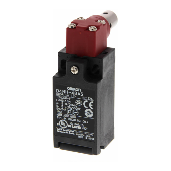
Miniature Safety-door Hinge Switch
D4NH
New series Safety-door Hinge
Switch Designed for sace saving
guaring in Machines and safety
Equipment
• Lineup includes three contact models with 2NC/1NO and
3NC contacts in addition to the 1NC/1NO, and 2NC ver-
sions. Version with MBB contacts meet applications for
avdanced requirements.
• M12-connector models are available, saving on labor and
simplifying maintenance.
• Standardized gold-clad contacts provide high contact reli-
ability Can be used with both standard loads and micro-
loads.
• Free of lead, cadmium, and hexavalent chrome, reducing the
burden on the environment.
Be sure to read the "Safety Precautions" on page G-214.
Model Number Structure
D4NH-@@@
1 2 3
1. Conduit/Connector size
1: Pg13.5 (1-conduit)
2: G1/2 (1-conduit)
3: 1/2-14NPT (1-conduit)
4: M20 (1-conduit)
5: Pg13.5 (2-conduit)
6: G1/2 (2-conduit)
7: 1/2-14NPT (2-conduit)
8: M20 (2-conduit)
9: M12 connector (1-conduit)
Application Examples (Protective Door Safety Measures)
Shaft Actuator
D4NH
Note: Contact your sales representative for details on models with safety standard
certification.
2. Built-in Switch
A: 1NC/1NO (slow-action)
B: 2NC (slow-action)
C: 2NC/1NO (slow-action)
D: 3NC (slow-action)
E: 1NC/1NO (MBB contact) (slow-action)
F: 2NC/1NO (MBB contact) (slow-action)
3. Actuator
AS:
BC:
Arm Lever Actuator
Shaft
Arm lever
G-207
Advertisement
Table of Contents

Related Manuals for Omron D4NH


Summary of Contents for Omron D4NH
- Page 1 • Free of lead, cadmium, and hexavalent chrome, reducing the burden on the environment. Be sure to read the “Safety Precautions” on page G-214. Note: Contact your sales representative for details on models with safety standard certification. Model Number Structure...
-
Page 2: Ordering Information
D4NH-8FBC Prefered types Note: 1. It is recommended that M20 be used for Switches to be exported to Europe and 1/2-14NPT be used for Switches to be exported to North American countries. 2. All models have slow-action contacts with approved direct opening mechanisms on NC contacts only. -
Page 3: Specifications
Note: 1. The values in the table on the previous page are initial values. 2. Once a contact has been used to switch a standard load, it cannot be used for a load of a smaller capacity. Doing so may result in rough- ening of the contact surface and contact reliability may be lost. - Page 4 33-34 can be used as unlike poles. Note: 1. Terminals are numbered according to EN50013. Contact forms are according to EN60947-5-1. 2. MBB (Make Before Break) contacts have an overlapping structure, so that before the normally closed contact (NC) opens, the normally open contact (NO) closes.
- Page 5 Movable contact Fixed contact (NO) Plunger Return spring Only the NC contact side has a direct opening mechanism. When metal deposition occurs, the contacts are separated from each other by the plunger being pushed in. (Conforms to EN60947-5-1 Direct Opening Operation.)
- Page 6 2. Variation occurs in the simultaneity of contact opening/closing operations of 2NC, 2NC/1NO, and 3NC contacts. Check contact operation. 3. There are a minimum of five turns of the screw thread for a Pg13.5 conduit opening and four turns minimum for a G 1/2 conduit opening.
- Page 7 2. Variation occurs in the simultaneity of contact opening/closing operations of 2NC, 2NC/1NO, and 3NC contacts. Check contact operation. 3. There are a minimum of five turns of the screw thread for a Pg13.5 conduit opening and four turns minimum for a G 1/2 conduit opening.
-
Page 8: Safety Precautions
Switch and must contact the machine manufacturer for any repairs Two-conduit Type or maintenance. Two, M4 • If the Switch is to be used in an emergency stop circuit or in a 2.5± safety circuit for preventing accidents resulting in injuries or deaths, 5.35±... - Page 9 To change the position, loosen the arm lever mounting screw, D4NH-@D@@ (3NC) D4NH-@F@@ (2NC/1NO (MBB)) dismount the arm lever, and mount the arm lever in the left or right position. Wiring • When connecting to the terminals via insulating tube and M3.5...
- Page 10 5311-1000 telegraphing when using adjustable or long levers. 1. Make the rear edge of the dog smooth with an angle of 15° to 30° Use LAPP connectors together with seal packing (JPK-16, GP-13.5, or make it in the shape of a quadratic curve.
- Page 11 Dimensions (Unit: mm) Discontinued Models (1-conduit D4DH) Replacement Products (1-conduit D4NH) 8.5±0.1 dia. Depth: 20 min. 2.15±0.05R (31.5) 28± Two, 3.2± dia. ±2 mounting holes 11± 8.5±0.1 dia. ±1 ±0.2 20.5×20.5 20.5×20.5 ±0.2 Depth: 20 min. 12.5 dia. ±0.2 12.5 dia.
- Page 12 ALL DIMENSIONS SHOWN ARE IN MILLIMETERS. To convert millimeters into inches, multiply by 0.03937. To convert grams into ounces, multiply by 0.03527. Cat. No. C131-E2-01A-X In the interest of product improvement, specifications are subject to change without notice. G-218 Safety Sensors / Components...
Need help?
Do you have a question about the D4NH and is the answer not in the manual?
Questions and answers