Advertisement
Multifunction actuator with 24 outputs (16 A)
ZIOMB24V2
FEATURES
•
6 different configurable blocks: shutter channels (up to 12),
individual outputs (up to 24) and 2-pipe fan coil control (up to 6)
•
Outputs suitable for capacitive loads, maximum 140 µF
•
Manual output operation with push button and LED status
indicator
•
2 Master Light controls
•
30 logic functions
•
Output timing
•
Total data saving on KNX bus failure
•
Integrated KNX BCU (TP1-256)
•
Dimensions 68 x 90 x 212 mm (12 DIN units)
•
DIN rail mounting according to IEC 60715 TH35, with fixing
clamp
•
Possibility of connecting different phases in adjacent outputs
•
Conformity with the CE, UKCA, RCM directives (marks on the right side)
1. Outputs
5. Programming/Test button
Programming/Test button: short press to set programming mode. If this button is held while plugging the device into the KNX bus, it enters the safe
mode. If this button is held for more than 3 seconds, the device enters the test mode.
Programming/Test LED: programming mode indicator (red). When the device enters the safe mode, it blinks (red) every half second. The manual mode
is indicated by the green color. During the start-up (reset or after KNX bus failure) and if the device is not in safe mode, it starts a blue blinking sequence.
GENERAL SPECIFICATIONS
CONCEPT
Type of device
Voltage (typical)
Voltage range
KNX supply
Maximum
consumption
Connection type
External power supply
Operation temperature
Storage temperature
Operation humidity
Storage humidity
Complementary characteristics
Protection class / Overvoltage category
Operation type
Device action type
Electrical stress period
Degree of protection / Pollution degree
Installation
Minimum clearances
Response on KNX bus failure
Response on KNX bus restart
Operation indicator
Weight
PCB CTI index
Housing material / Ball pressure test temperature
¹ Maximum consumption in the worst-case scenario (KNX Fan-In model).
© Zennio Avance y Tecnología S.L.
2. Output status LED
6. Programming/Test LED
Voltage
29 VDC (typical)
24 VDC¹
Edition 1
1
2
3
3. Output control button
DESCRIPTION
Electric operation control device
29 VDC SELV
21-31 VDC
mA
4.3
10
Typical TP1 bus connector for 0.8 mm Ø rigid cable
Not required
0 .. +55 °C
-20 .. +55 °C
5 .. 95%
5 .. 95%
Class B
II / III (4000 V)
Continuous operation
Type 1
Long
IP20 / 2 (clean environment)
Independent device to be mounted inside electrical panels with DIN rail (IEC
60715)
Not required
Data saving according to parameterization
Data recovery according to parameterization
The programming LED indicates programming mode (red) and test mode
(green). Each output LED indicates its status.
757 g
175 V
PC FR V0 halogen free / 75 °C (housing) - 125 °C (connectors)
Further information
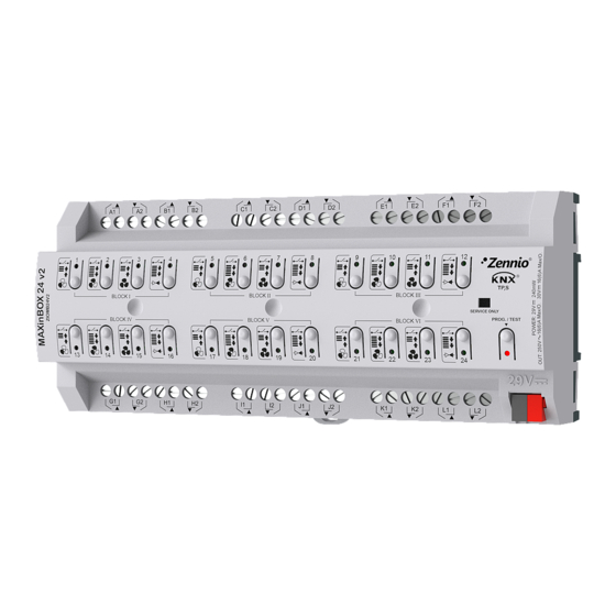
MAXinBOX 24 v2
TECHNICAL DOCUMENTATION
4
5
6
Figure 1: MAXinBOX 24 v2
4. Fixing clamp
7. KNX connector
mW
124.7
240
www.zennio.com
7
Page 1/2
Advertisement
Table of Contents

Related Manuals for Zennio MAXinBOX 24 v2


Summary of Contents for Zennio MAXinBOX 24 v2
- Page 1 DIN rail mounting according to IEC 60715 TH35, with fixing clamp • Possibility of connecting different phases in adjacent outputs Figure 1: MAXinBOX 24 v2 • Conformity with the CE, UKCA, RCM directives (marks on the right side) 1. Outputs 2.
- Page 2 • The WEEE logo means that this device contains electronic parts and it must be properly disposed of by following the instructions at https://www.zennio.com/en/legal/weee-regulation. • This device contains software subject to specific licences. For details, please refer to http://zennio.com/licenses. © Zennio Avance y Tecnología S.L.
Need help?
Do you have a question about the MAXinBOX 24 v2 and is the answer not in the manual?
Questions and answers