
Subscribe to Our Youtube Channel
Related Manuals for Schmalz VacuMaster VM-BASIC


Summary of Contents for Schmalz VacuMaster VM-BASIC
- Page 1 VacuMaster VM-BASIC Horizontal (Electrical) Operating Instructions WWW.SCHMALZ.COM EN-US · 30.30.01.01610 · 00 · 01/20...
- Page 2 Published by © J. Schmalz GmbH, 01/20 This document is protected by copyright. J. Schmalz GmbH retains the rights established thereby. Repro- duction of the contents, in full or in part, is only permitted within the limits of the legal provisions of copyright law. Any modifications to or abridgments of the document are prohibited without explicit writ- ten agreement from J. Schmalz GmbH.
-
Page 3: Table Of Contents
Contents Contents 1 Important Information ........................... 6 1.1 The technical documentation is part of the product ................ 6 1.2 Note on Using these Operating Instructions .................. 6 1.3 Other Applicable Documents ........................ 6 1.4 Warnings in this document........................ 6 1.5 Symbol.............................. 6 1.6 Information Signs on the Lifting Device .................... - Page 4 Contents 6.1.2 Protective Equipment........................ 21 6.2 Mounting the Operator Handle ...................... 21 6.3 Attaching the Parking Stands...................... 23 6.4 Electrical Connection.......................... 23 6.5 Checking the Rotating Field ........................ 24 6.6 Fastening the Lifting Device ........................ 25 6.7 Start of Operations.......................... 25 7 Operation .............................. 26 7.1 Safety ..............................
- Page 5 Contents 9.5 Cleaning the Dust Filter ........................ 45 9.6 Checking the Suspension Eye for Wear .................... 45 9.7 Cleaning the lifting device........................ 45 9.8 Replacing Suction Plates ........................ 46 10 Decommissioning and Recycling........................ 47 10.1 Safety .............................. 47 10.2 Decommissioning the Lifting Device.................... 47 10.3 Disposing of the Lifting Device ......................
-
Page 6: Important Information
ð Failure to follow the instructions in these Operating instructions may result in life-threatening in- juries! ð Schmalz is not liable for damage or malfunctions that result from failure to heed these instructions. If you still have questions after reading the technical documentation, contact Schmalz Service at: www.schmalz.com/services... -
Page 7: Information Signs On The Lifting Device
Important Information ü This symbol represents a prerequisite that must be met prior to an operational step. 4 This symbol represents an action to be performed. ð This symbol represents the result of an action. Actions that consist of more than one step are numbered: 1. -
Page 8: Type Plate
Important Information Manual slide valve Holder for the chain hoist con- 27.03.01.00379 trol pendant 27.03.01.00464 Switching off the suction plates reduces the lift capacity (op- tional) 27.03.01.00393 Water separator (optional) 27.03.01.00772 1.7 Type Plate The type plate is permanently attached to the product and must always be clearly legible. For each product, the type plate contains the following data: •... -
Page 9: Fundamental Safety Instructions
Do not exceed the maximum permissible lift capacity (see type plate). 2.2 Non-Intended Use Schmalz accepts no liability for damage caused by the use of the lifting device for purposes other than those described under Intended Use. The use of the lifting device for loads that are not specified in the order confirmation or that have different physical properties than those specified in the order confirma- tion shall be considered non-intended use. -
Page 10: Environmental And Operating Conditions
4 Do not pick up liquids or bulk materials. 4 Observe the gauge and the signal from the warning device. 4 If the suction of liquids cannot be avoided, use a water separator (contact Schmalz ser- vice). The lifting device VacuMaster may only be operated under the following conditions: •... -
Page 11: Workplace Requirements
Work on electrical equipment must be carried out only by qualified electrical specialists. • Installation, maintenance, and repairs must be carried out only by specialists from J. Schmalz GmbH or by persons who can prove that they have undergone appropriate training at Schmalz. The following target groups are addressed in these operating instructions: •... -
Page 12: Safety Features
• Safety features must not be disabled under any circumstances. Schmalz assumes no liability for consequences of modifications over which it has no control. 2.12 Responsibility of the Operating Company The operating company is also responsible for third parties in the working area of the lifting device. The operating company must ensure that they have the appropriate qualifications and skills. -
Page 13: Product Description
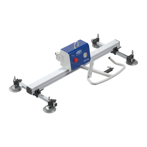
Product Description 3 Product Description 3.1 VacuMaster Basic Horizontal Components VacuMaster Basic Horizontal with electrical vacuum generation 11.1 Suspension eye Main switch Manual slide valve Vacuum gauge Operator handle Holder for the chain hoist control pen- dant Suction plate Clamping lever for suction plate holder Suction plate holder Vacuum pump Main beam with vacuum distributor... - Page 14 Product Description 11.1 Components not shown: • Warning device in the control box • Non-return valve 3.2 Manual slide valve Manual slide valve for VacuMaster Basic Use of the manual slide valve: • Applying suction to the load: Press the locking button and slide the manual slide valve (3) in the direction with the aid of the spring.
-
Page 15: Suction Plates
Product Description 3.3 Suction Plates The suction plates (6) are used to pick up loads. The suction plate that is used depends on the load (weight, geometry and surface properties). All suction plates must be entirely on the workpiece in order to generate a vacuum and to be able to lift the loads. -
Page 16: Movable Operator Handle (Optional)
Product Description The passage to the vacuum reservoir is open. The vacuum reservoir is closed. The vacuum is present at the suction plate. The suction plate is vented. Suction plates can be switched off: The permissible lift capacity per suction plate must not be exceeded. -
Page 17: Parking Stand (Optional)
Product Description 3.4.4 Parking Stand (Optional) To protect the suction plates, the lifting device can be set on its parking stands (17) (for lifting devices with a maximum lift capacity of 2,000 kg). 3.4.5 Multiple Eye for Center of Gravity Compensation (Optional) A multiple eye (1) is designed to balance the lifting device according to the position of the center of grav- ity. -
Page 18: Technical Data
Technical Data 4 Technical Data 4.1 Lifting Device For technical data, see the type plate. 4.2 Vacuum Generation For technical data, see the type plate on the vacuum generator. 18 / 50 EN-US · 30.30.01.01610 · 00 · 01/20... -
Page 19: Transport And Storage
1. Compare the entire delivery with the supplied delivery notes to make sure nothing is missing. 2. Damage caused by defective packaging or occurring in transit must be reported immediately to the carrier and Schmalz. 5.3 Removing the Packaging The device is supplied shrink wrapped on a pallet. -
Page 20: Storing The Lifting Device
Transport and Storage 5.5 Storing the Lifting Device If the lifting device is not used for an extended period, it must be stored correctly to protect it from dam- age. Options for correct storage: 1. Let the lifting device hang close to the ground. 2. -
Page 21: Installation
Installation 6 Installation 6.1 Safety 6.1.1 Safety Instructions for Installation The lifting device must be installed and maintained only by qualified specialist electricians and mechanics. WARNING Improper mounting Serious injury or death! 4 Carry out mounting and removal only when the device is in an idle, depressurized state. - Page 22 Installation 2. Attach the operator handle (5) to the sliding block under the basic module (13) with hexagon screws and spring washers. 3. Connect the longer hose end to the man- ual slide valve (3). 4. Connect the short hose end to the opera- tor handle pipe (5).
-
Page 23: Attaching The Parking Stands
Installation 6.3 Attaching the Parking Stands Attach the parking stands to both ends of the main beam (8) according to the following instructions. 1. Unscrew the sealing caps (8.2) from the main beam. 2. Push both sliding blocks (17.1) into the upper slots of the main beam. -
Page 24: Checking The Rotating Field
4. Check the direction of rotation once again. You can purchase a motor rotation tester from Schmalz (part no. 21.05.05.00082). Schmalz ac- cepts no liability for damage caused by operating the device with the incorrect direction of ro- tation. -
Page 25: Fastening The Lifting Device
Installation 6.6 Fastening the Lifting Device 1. Ensure that the lift capacity of the hoist (crane or chain hoist) is at least equal to the sum of the lift- ing device’s weight and lift capacity (refer to the type plate). 2. Fasten the load hook of the hoist (chain hoist) to the lifting device suspension eye (1). 6.7 Start of Operations 1. -
Page 26: Operation
Operation 7 Operation 7.1 Safety 7.1.1 Safety Instructions for Operation DANGER Falling objects while handling above 1.8 m Serious injury or death! 4 While handling loads with a swiveling point that is above 1.8 m, cordon off the work- ing area. 4 Wear an industrial helmet. WARNING Falling objects Serious injury or death! -
Page 27: What To Do In An Emergency
Operation • Use the operator handle only to guide the lifting device. Do not attempt to compensate for swivel- ing or tilting motions using the operator handle. • Do not lift, drag or pull loads at an angle. • Do not use the lifting device to free stuck loads. •... -
Page 28: Checks Before Starting Work
Operation 7.1.6 Checks before Starting Work 1. Ensure that the energy supply is operating reliably. 2. Inspect safety features. 3. Drain the water separator (optional). 7.2 Adjusting the Position of the Suction Plates 11.1 Suction plate Clamping lever for suction plate Suction plate holder Main beam with vacuum distributor Cross beam 11.1... -
Page 29: Correctly Aligning Three Cross Beams For Non-Rigid Loads
Operation Only 2 suction plates are carrying the All suction plates are carrying the load load The center suction plates are inactivated and not carrying the load All suction plates are on the same level 7.3.1 Correctly Aligning Three Cross Beams for Non-Rigid Loads For non-rigid loads that are longer than the main beams (8), the cross beams (11) must be correctly aligned to an imagined line of symmetry: Incorrect alignment of the cross beams... -
Page 30: Correctly Aligning Four Cross Beams For Non-Rigid Loads
Operation 2. Align the two outer cross beams (11) such that the suction plates are positioned in the center of the outer areas. ð This ensures an even distribution of the load. 7.3.2 Correctly Aligning Four Cross Beams for Non-Rigid Loads For non-rigid loads that are longer than the main beams (8), the cross beams (11) must be correctly aligned to an imagined line of symmetry: Incorrect alignment of the cross beams... -
Page 31: Switching Suction Plates On/Off (Optional)
Operation 7.4 Switching Suction Plates On/Off (Optional) WARNING Switching off suction plates with picked up load Severe injury or death due to falling loads. 4 Do not close or open the manual slide valves while a load is attached. CAUTION Reduced lift capacity due to suction plates being switched off Serious injury! 4 The permissible lift capacity of the lifting device decreases in proportion to the number of suction plates switched off. -
Page 32: Movable Operator Handle With Pressure Spring (Optional)
Operation 7.5 Movable Operator Handle with Pressure Spring (Optional) 1. Press the control lever (9) and simultaneously swivel the operator handle (5) to the desired position. 2. Release the control lever (9). 7.6 Putting the Parking Stands into the Working Position (Optional) Fold up both parking stands before handling. -
Page 33: Balancing The Center Of Gravity (Optional)
Operation 17.2 3. Ensure that the handle is securely engaged. 7.7 Balancing the Center of Gravity (Optional) The load hook can be attached to one of the suspension eyes (1). Different suspension eyes can be chosen to adjust the balance of the lifting device for different loads. WARNING Uncontrolled swinging movements during lifting Risk of serious injury... -
Page 34: Raising The Load
Operation Lifting device balanced Hang the load further to the Hang the load further to the left right 7.8 Raising the Load WARNING Falling objects due to insufficient vacuum Serious injury or death! 4 Before lifting the load, ensure that the minimum vacuum of -0,6 bar has been attained. WARNING Uncontrolled swinging movements during lifting Serious injury can result! -
Page 35: Safely Guiding The Lifted Load
Operation 3. Position the lifting device over the load’s cen- ter of gravity. 4. Carefully lower the lifting device onto the load. 5. Ensure that all suction plates are completely in contact with the load. 6. Ensure that any uncovered suction plates are switched off and that all suction plates cov- ered by the load are switched on. -
Page 36: Setting Down The Load
Operation CAUTION Risk of injury due to collision! 4 Walk behind the lifting device in the direction of travel while maintaining the pre- scribed safe distances. Observe the following while a load is lifted: • Never transport loads above people. •... -
Page 37: Putting The Parking Stands Into The Parked Position (Optional)
Operation 4. Alternatively, hang the lifting device from the hoist in a safe position close to the ground. Ensure that the hoist cannot be used by unauthorized persons. 5. If the lifting device cannot be parked close to the ground, then block off the danger zone under- neath it. -
Page 38: Troubleshooting
Troubleshooting 8 Troubleshooting 8.1 Safety 8.1.1 Safety Instructions for Troubleshooting Faults in the lifting device may only be repaired by qualified mechanics and electricians. Personnel must have read and understood the operating instructions. DANGER Electric shock from touching live components Serious injury or death! 4 Make sure that the electrical components are not live before installation, maintenance and troubleshooting. - Page 39 Gauge is faulty. 4 Seal or replace compo- Hose or screw unions are leaking. nents. 4 Contact Schmalz service. Vacuum switch is obstructed or faulty. 4 Observe the maximum al- Location of use is higher than 1600 m above sea level.
- Page 40 3. Check the motor for faults. 4 Check the vacuum gener- The vacuum generator is faulty. ator and contact Schmalz service if necessary. Optional movable operator External influence (accident, 1. Decommission the lifting handle: The gas pressure collision, extreme overload- device.
-
Page 41: Maintenance
Maintenance 9 Maintenance 9.1 Safety 9.1.1 Safety Instructions for Maintenance The lifting device must be installed and maintained only by qualified specialist electricians and mechanics. Personnel must have read and understood the operating instructions. DANGER Electric shock from touching live components Serious injury or death! 4 Make sure that the electrical components are not live before installation, maintenance and troubleshooting. -
Page 42: Maintenance Schedule
As a special service within Germany, J. Schmalz GmbH offers an inspection contract for an an- nual test with a certificate from an expert. Please refer to the seal of approval attached to the system for more information. -
Page 43: Maintenance Schedule For The Electrics
Maintenance Maintenance task Daily Weekly Monthly Every six Yearly months Check the condition of the hose con- nections. Check all load-bearing parts (e.g. sus- pension) for deformation, wear or other damage. Grease manual slide valve Lubricate the manual slide valve for switching on the suction plates Check the suspension eye for deforma- tion, wear or other damage. -
Page 44: Checking Vacuum Hoses And Hose Clamps
Maintenance ü The manual slide valve (3) is closed. ü All manual slide valves (6.3) on the suction plates are closed (optional switchable manual slide valves). 1. Switch on the vacuum generator. ð A warning signal sounds until the minimum vacuum of -0,6 bar is reached. 2. -
Page 45: Draining The Water Separator (Optional)
Maintenance 9.4.5 Draining the Water Separator (Optional) 1. Ensure that the vacuum generator is switched off and no residual vacuum is in the vacuum reservoir. 2. Drain the water separator. 9.5 Cleaning the Dust Filter DANGER Falling load. If the dust filter is clogged, the warning device will not trigger even though the vacuum at the suction pad is insufficient. -
Page 46: Replacing Suction Plates
Maintenance NOTE Moisture ingress Damage to the electronics! 4 During cleaning, make sure that no moisture gets into the electronics. • The suction plates must be cleaned at least once per week with an agent containing active tensides (pH-neutral). • Also clean mechanically (soft brush or ultrasonic cleaning). -
Page 47: Decommissioning And Recycling
4 Do not dispose of the gas pressure spring without letting off the pressure. 4 Cover the drilled hole. 4 Wear eye protection. Schmalz will assist you with the disposal of the gas pressure spring upon request. 1. Disassemble the gas pressure spring. EN-US · 30.30.01.01610 · 00 · 01/20... - Page 48 Decommissioning and Recycling 2. Slowly drill at point X1 = 40 mm on the ex- tended gas pressure spring (2–3 mm hole di- ameter). 3. Slowly drill at point X2 = 35 mm (2–3 mm hole diameter). 4. Ensure that the gas pressure spring is depres- surized by slightly moving the piston rod.
-
Page 49: Ec Conformity
EC Conformity 11 EC Conformity EC declaration of conformity The manufacturer Schmalz confirms that the lifting device VacuMaster Basic Horizontal described in these operating instructions fulfills the following applicable EC directives: 2006/42/EC Machinery Directive 2014/30/EU Electromagnetic Compatibility 2014/35/EU Low Voltage Directive The following harmonized standards were applied: EN ISO 12100...
Need help?
Do you have a question about the VacuMaster VM-BASIC and is the answer not in the manual?
Questions and answers