Advertisement
Shooting Board
®
The Veritas
Shooting Board comes fully assembled; however, it is necessary to adjust
the parts to fi t your shooting plane and to set the fence for accurate cuts. As you use
the shooting board, it may be necessary to periodically repeat these steps to maintain
accurate results.
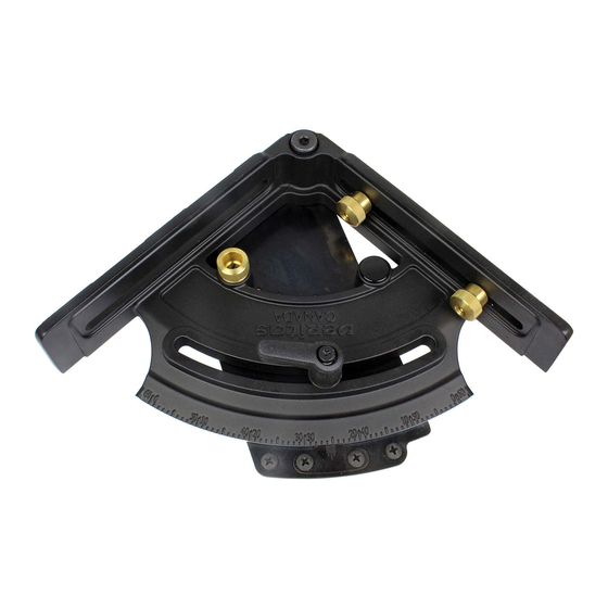
Adjusting
Set Screws
Shooting Fence
Figure 1: Shooting board components.
Adjusting the Track
The fi rst step is to set the track to fi t your shooting plane. Loosen the pan-head screws
that hold the rail in place. Back the adjusting set screws off so that your plane can fi t
in the track. To set a small amount of clearance, place a piece of paper between the
rail and the plane and adjust the set screws until the shooting plane is suitably captured
in the track base, but can still move freely along it. Tighten the pan-head screws and
remove the paper.
Shooting Plane
Pan-Head Screws
Figure 2: Adjusting the track.
Shooting Track
Adjusting Set Screws
1
Shooting Board
Rail
Paper
Advertisement
Table of Contents

Related Manuals for VERITAS 325650


Summary of Contents for VERITAS 325650
- Page 1 Shooting Board ® The Veritas Shooting Board comes fully assembled; however, it is necessary to adjust the parts to fi t your shooting plane and to set the fence for accurate cuts. As you use the shooting board, it may be necessary to periodically repeat these steps to maintain accurate results.
- Page 2 Adjusting the Fence Loosen the gyratory handle and the four #8 screws that hold the detent plate and zero scale in place. Ensure the spring plunger is engaged in the detent plate so that the fence and plate move together. Place an accurate square between the plane’s sole and the fence.
- Page 3 Middle graduation on the zero scale 0˚ graduation Figure 5: Locating and locking the zero scale. The shooting board fence can be set accurately to within 0.25°. 0.5° 0.25° 0° Figure 6: Setting the fence angle.
- Page 4 " 2 × Ø " THRU " × 82˚ " " 3" " " Figure 7: Dimensions for a sub-fence. Veritas Tools Inc. Ottawa ON K2H 1C2 Canada veritastools.com © Veritas Tools Inc. 2018 649 INS-701_B...
Need help?
Do you have a question about the 325650 and is the answer not in the manual?
Questions and answers