
Related Manuals for Federal Signal Corporation SmartSystem SS2000C31


Summary of Contents for Federal Signal Corporation SmartSystem SS2000C31
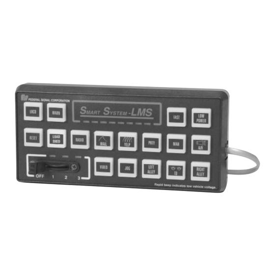
- Page 1 Model SS2000C31 SmartSystem™ Load Management System LOAD MANAGER WITH ELECTRONIC SIREN/LIGHT CONTROL SYSTEM AND DIRECTIONAL LIGHT (with Slide Switch Control Head) OPERATION AND CONFIGURATION INSTRUCTIONS...
-
Page 2: Limited Warranty
LIMITED WARRANTY The Signal Division, Federal Signal Corporation (Federal), warrants each new product to be free from defects in material and workmanship, under normal use and service, for a period of two years on parts replacement and one year on labor from the date of delivery to the first user-purchaser. -
Page 3: Operation
OPERATION SmartSystem-LMS LRC O WARN FAST LOPWR STBY WAIL YELP PRTY HI IDL OFF 1 290A4318-01 Although it is extremely versatile, Slide Switch Position 1 - Activates MAN - Will produce peak & hold the SmartSystem-LMS (Model relay 1 and Warn-1 on directional tone when no other sirens are active. - Page 4 SS2000C31 Features CONFIGURATION • Combined load management/ electronic siren and light con- WARNING trol. Property damage, serious injury, or death to you or others may • Programmable load shedding at result if the SS2000C31 is improperly configured. Configura- the point of installation. tion, if required, is to be performed at the time of installation.
-
Page 5: Configuration Tree
CONFIGURATION TREE LEVEL 4 LEVEL 5 LEVEL 1 LEVEL 2 LEVEL 3 Load Management Keyboard Keys / Switches Horn Ring Power Up Select Voltage Threshold Set Sirens Independent. for Load Manager: Select Horn Ring Transfer Default Configuration. Select which keys Function •... - Page 7 SECTION IV OPERATION SAFETY MESSAGE TO OPERATORS OF FEDERAL SIGNAL ELECTRONIC SIRENS AND LIGHT/SOUND SYSTEMS • Frequently inspect the speaker to ensure that WARNING it is clear of any obstruction, such as mud or The lives of people depend on your safe snow, which will reduce maximum sound operation of Federal products.
- Page 8 MAIN MENU SmartSystem-LMS SAVE LEVEL 1 LEVEL 3 LEVEL 4 LEVEL 5 LEVEL 2 OFF 1 290A4318-02 Entering The “MAIN MENU” will come up on the keyboard as soon as you enter LEVEL 2 Configuration Mode configuration mode. Keys 10, 11, 12, 13, and 14 buttons will be solidly il- Pressing “LEVEL 2”...
- Page 9 LEVEL 1 (Keyboard) SmartSystem-LMS Function Configuration Sirens Default Directional SAVE Indicator Mode Independent Configuration Light Sound Disable OFF 1 290A4318-03 LEVEL 1 (Keyboard) is where op- Directional Light 6 default settings (see OPERATION, tions are chosen that affect the en- page 1).
- Page 10 LEVEL 2 (Keys) SmartSystem-LMS Aux. Relay Siren Slide SAVE Keys Disable Switches OFF 1 290A4318-04 Level 2 (Keys) is used to specifically Slide Switches Siren Disable configure each key or switch. Level 2 allows you to change how each Pressing “Slide Switches” (Key 13) Pressing “Siren Disable”...
- Page 11 LEVEL 2 - Slide Switches SmartSystem-LMS SAVE Slide 1 Slide 3 Slide 2 OFF 1 290A4318-05 Level 2 Slide Switches determines Slide 1 If Slide 2 is selected, go to Level 2 - which Slide Switch position to Slide Switch - Function, page 10, to reconfigure.
- Page 12 LEVEL 2 - Slide Switch - Function Directional Directional Directional Directional SmartSystem-LMS Light Light Light Light Warn - 1 Warn - 2 Warn - 3 Warn - 4 Horn Ring Relay 3 Relay 1 Relay 2 Siren Transfer SAVE Enable Enable Aux.
- Page 13 LEVEL 2 - Aux Relay Keys SmartSystem-LMS SAVE Aux. Relay Aux. Relay Aux. Relay Aux. Relay Aux. Relay OFF 1 290A4318-07 Level 2 - Aux Relay Keys determines Aux Relay B Aux Relay D which Aux Relay Key to reconfigure. Press “Aux Relay B”...
- Page 14 LEVEL 2 - Aux Relays - Function SmartSystem-LMS Push-on/ 8-Second Security SAVE Momentary Timer Timer Push-off OFF 1 290A4318-08 Level 2 - Auxiliary Keys - Function configuring to act as a standard Security Timer is where you decide how the Auxil- Push On / Push Off switch.
- Page 15 LEVEL 2 - Siren Enable/Disable SmartSystem-LMS SAVE Manual Wail Yelp Hi-Lo Radio Air Horn Priority OFF 1 290A4318-09 Level 2 - Siren Enable/Disable is H/L or PRIORITY where you can enable or disable si- ren tones and radio rebroadcast. WAIL Key 14 can be configured to activate either the High Low tone or the Pri- This is also where you choose be-...
- Page 16 LEVEL 3 (Power Up) SmartSystem-LMS SAVE OFF 1 290A4318-10 Level 3 - Power Up is where you de- Turn on the keys you want to turn Note cide what keys should turn on auto- on automatically when the system matically when the system is turned is powered up.
- Page 17 LEVEL 4 (Horn Ring) SmartSystem-LMS No Siren Active Tone Horn Ring Transfer Tone 8-Second SAVE Timeout Priority Peak & Hold Air Horn Yelp OFF 1 290A4318-11 Level 4 - Horn Ring is where you 8-Second Timeout Activate key 13 if you want YELP to decide how you want the horn ring be this tone.
- Page 18 LEVEL 5 Load Management SmartSystem-LMS Higher Load High Idle Voltage Voltage Voltage Shed SAVE Control Settings Threshold Alarm Sequence Enable Enable Enable Lower Common Voltage Microphone Settings Control Enable Enable OFF 1 290A4318-12 Level 5 - Load Management is where you thresholds.
- Page 19 LEVEL 5 Load Shed Sequence SmartSystem-LMS Aux. Relay Aux. Relay Aux. Relay Reset SAVE (No Shed) Aux. Relay Aux. Relay Aux. Relay Aux. Relay Aux. Relay OFF 1 290A4318-13 Level 5 - Load Shed Sequence is manager will NOT shed relays Previously shed loads can be re- where you decide which relays which are NOT in the shedding se-...
- Page 20 LEVEL 5 Voltage Threshold SmartSystem-LMS Enable lower Enable Higher Voltage Voltage SAVE Threshold Threshold Programming Programming High Load Voltage Idle Shed Alarm Threshold Threshold Threshold OFF 1 290A4318-14 Level 5 - Voltage Threshold is where you con- To perform the voltage threshold program- to enable voltage threshold programming.
- Page 21 Load Management Flow Chart EXIT Subroutine for Load Management Volts > 12.8V Vehicle in PARK? for 30 sec.? Volts < 12.8V Is Low Voltage Alarm On? for 30 sec.? Was High Idle turned on? Turn Low Voltage Alarm Off Volts > 13.8V Shed load according to the for 30 sec.? programmed sequence...
- Page 22 Worksheet Level 1 Sirens independent of slide switch Function Indicator Sound Directional light Type 6-Lamp 8-Lamp Level 2 - Keys/Switches Slide Switch (Circle any combination for each slide switch position.) Relays Auxiliary Relays Misc. SignalMaster Warn Pattern Position 1 HRTR SIREN Position 2 HRTR...
- Page 23 Relay/Device Assignments List below which controlled devices are connected to which relay. Relay 1 (20-amperes max.) Relay 2 (20-amperes max.) Relay 3 (40-amperes max.) Relay A (10-amperes max.) Relay B (10-amperes max.) Relay C (10-amperes max.) Relay D (10-amperes max.) Relay E (10-amperes max.) Is Horn Ring Transfer used? Is the Radio Rebroadcast Switch used?
- Page 24 255352A Printed in U.S.A. REV. A 903...
Need help?
Do you have a question about the SmartSystem SS2000C31 and is the answer not in the manual?
Questions and answers