Table of Contents
Advertisement
Quick Links
2562118D REV. D 911
Safety Message to Installers and Service Personnel of Warning
Light Equipment
People's lives depend on your proper installation and servicing of Federal Signal products. It is important to
read and follow all instructions shipped with this product and the original product. In addition, listed below
are some other important safety instructions and precautions you should follow:
• To properly install this device, you must have a good understanding of automotive electrical procedures
and systems, along with proficiency in the installation and use of safety warning equipment.
• DO NOT install equipment or route wiring in the deployment path of an airbag.
• If a vehicle seat is temporarily removed, verify with the vehicle manufacturer if the seat needs to be
recalibrated for proper airbag deployment.
• When drilling into a vehicle structure, be sure that both sides of the surface are clear of anything that
could be damaged.
• In order for the device to function properly, a good ground connection must be made. At a minimum, it
must be attached to a solid metal body or chassis part that will provide an effective ground path as long
as the light system is to be used.
• Locate light control so the VEHICLE and CONTROL can be operated safely under all driving
conditions.
• Do not attempt to activate or deactivate light control while driving in a hazardous situation.
• This product controls high intensity lighting devices. To prevent eye damage, DO NOT stare into the
light beam at close range.
• You should frequently inspect the light to ensure that it is operating properly and that it is securely
attached to the vehicle.
• File these instructions in a safe place and refer to them when maintaining and/or reinstalling the product.
Failure to follow all safety precautions and instructions may result in property damage, serious injury, or death.
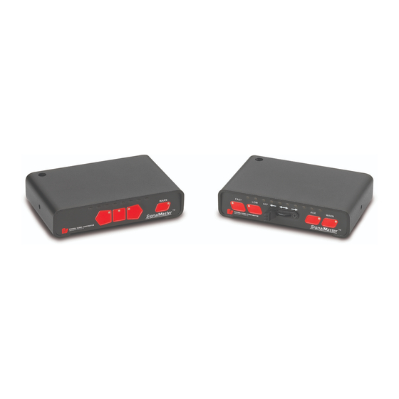
Overview
The Model 330104 SMC1 is a directional light controller. It is designed to operate the full selection of
Federal Signal SignalMaster
at 12 V or 24 V. The control circuitry is protected against reverse polarity by a 2 A fuse and a diode. The
lightbar requires its own appropriately-sized fuse.
This model provides six distinctive directional signals. There are standard left-arrow, center-out, and right-
arrow patterns as well as special left-arrow, center-out, and right-arrow patterns that comply with CAC Title
13, Article 22 if used with the appropriate SignalMaster directional lightbar in Tables 1 and 2 on page 2.
®
directional lightbars from four to eight light heads, either continuous or split,
Instructions for the Model 330104 SMC1
SignalMaster® Lightbar Controller
Advertisement
Table of Contents

Subscribe to Our Youtube Channel
Related Manuals for Federal Signal Corporation SignalMaster 330104 SMC1


Summary of Contents for Federal Signal Corporation SignalMaster 330104 SMC1
- Page 1 Instructions for the Model 330104 SMC1 SignalMaster® Lightbar Controller 2562118D REV. D 911 Safety Message to Installers and Service Personnel of Warning Light Equipment People’s lives depend on your proper installation and servicing of Federal Signal products. It is important to read and follow all instructions shipped with this product and the original product.
- Page 2 Installation and Programming Instructions Table 1 Halogen SignalMaster directional warning lights (for CAC Title 13, Article 22 compliance) Model Length Lamps Cable Lenses 320142 20 in 30 ft Amber 320162 31 in 15 ft Amber 320612 31 in 30 ft Amber 320172 42 in...
- Page 3 Installation and Programming Instructions Model 330104 Controller Specifications Electrical Input Voltage: 11 Vdc to 28 Vdc Polarity: Negative ground only Operating Temperature Range: –30 °C to +65 °C Standby Current: 7 mA (0.007 A) Lightbar Fuse: 20 A, installer-provided +IGNITION Fuse: Output Drive Capability (Total): Eight 27 W lamps on 8 channels Normal Directional Flash Rate: Approximately 30 patterns per minute Dimensions...
-
Page 4: Connecting Power To The Controller
Installation and Programming Instructions DRILLING PRECAUTIONS—When drilling holes, check the area into which you are drilling to be sure that you do not damage vehicle components. All drilled holes should be deburred and all sharp edges should be smoothed. All wire routing going through drilled holes should be protected by a grommet or convo- lute/split-loom weaving. - Page 5 Installation and Programming Instructions To make the power connections to the controller: 1. Strip 1/4" of insulation from the main ground wire and crimp the proper spade connector onto it. BATTERY EXPLOSION—To avoid a battery explosion, always disconnect the negative battery cable first and reconnect it last. Avoid causing a spark when connecting near or to the battery. The gases produced by a battery can cause a battery explosion that could result in vehicle damage and serious injury.
- Page 6 Installation and Programming Instructions 6. Strip 1/4" of insulation from all of the wires that will enter nine-position the terminal block. Make all of the required connections to the terminal block as described in the next section. 7. Connect the 18 AWG red wire to the position labeled on the terminal block for +12-24 Vdc. Wiring the Six- and Eight-Head SignalMaster To wire the SignalMaster: 1. Connect the colored wires from the nine-conductor cable to the locations specified in Figure 2 or on the label affixed to the controller housing. NOTE: With the six-head SignalMaster lightbar, the white and blue wires are not needed and can be cut even with the cable sheath. 2. For split SignalMasters where two-, three- or four-head assemblies make up a full eight- or six-head SignalMaster assembly, connect the wires to the terminal blocks in order from left to right. The output labeled BLUE on the controller is for the rightmost lamp, and the one labeled WHITE is for the leftmost lamp. 3. When all electrical connections are completed, insert a 20 A fuse into the fuse holder in the SignalMaster red power wire. Figure 2 Wiring from SignalMaster to controller BINDING SCREW FOR GROUND WIRE BLACK...
-
Page 7: Mounting The Controller
Installation and Programming Instructions Mounting the Controller To fasten the controller to the bracket: 1. Place the controller into the mounting bracket (Figure 1 on page 4). 2. Fasten the controller using the two self tapping screws provided. 3. Angle the controller for optimum visibility from the operators position before tightening the screws. 4. Dress the cables and wires, and secure them out of the way. Configuring the Controller The controller has several installer-selectable warning patterns that you can select after the installation and wiring of the SignalMaster system is complete. For the functions of the controller buttons, see Figure 3 and. “Operating the SignalMaster Controller” on page 9. Figure 3 Model 330104 SMC1 controller SIGNALMASTER LED INDICATOR CENTER OUT LEFT ARROW RIGHT ARROW... -
Page 8: Entering Program Mode
Installation and Programming Instructions Table 6 Warn patterns compliant with CAC Title 13, Article 22 Pattern Description Null (no pattern) Alternating, two-head flash on each end Alternating in/out Alternating odds/evens Entering Program Mode With the vehicle ignition turned on and the directional light turned off, press the LEFT ARROW and CENTER OUT buttons simultaneously. Both buttons remain lit indicating that the controller is now in Programming Mode. Select one or more of the following options before exiting Program Mode. See “Exiting Program Mode” at the end of this section. Selecting a Six- or Eight-Head Output ■... - Page 9 Installation and Programming Instructions Safety Message to Operators of Warning Light Equipment Peoples’ lives depend on your safe use of our products. Listed below are some important safety instructions and precautions you should follow: • Do not attempt to activate or de-activate the light system control while driving in a hazardous situation. • Although your warning system is operating properly, it may not be completely effective. People may not see or heed your warning signal. You must recognize this fact and continue driving cautiously. • Also, situations may occur which obstruct your warning signal when natural or manmade objects are between your vehicle and others, such as: raising your hood or trunk lid. If these situations occur, be especially careful. • This product controls high intensity LED devices. To prevent eye damage, DO NOT stare into the light beam at close range. • At the start of your shift you should ensure that the light is securely attached and all lamps are operating properly. The LED display on the control only simulates the operation of the lamps. • If a selected function does not perform properly or if any of the lamps remain illuminated when the control is off, disconnect the power connector from the controller and contact the nearest service center. Failure to follow these safety precautions may result in property damage, serious injury, or death.
-
Page 10: Testing The Installation
Installation and Programming Instructions Testing the Installation LIGHT HAZARD—To be an effective warning device, an emergency warning system produces bright light that can be hazardous to your eyesight when viewed at a close range. Do not stare directly into the lights at a close range or permanent damage to your eyesight may occur. -
Page 11: Returning A Product To Federal Signal
Installation and Programming Instructions Returning a Product to Federal Signal Before returning a product to Federal Signal, call 800-264-3578, 800-433-9132, or 800-824-0254 to obtain a Returned Merchandise Authorization number (RMA number). To expedite the process please be prepared with the following information: • Your Federal Signal customer or account number. • The purchase order number under which the items were purchased. • The shipping method. • The model or part number of the product being returned. • The quantity of products being returned. • Drop ship information as needed. • Any estimate required. When you receive your RMA Number: • Write the RMA number on the outside of the box of returned items. • Reference the RMA number on your paperwork inside of the box. • Write the RMA number down, so that you can easily check on status of the returned equipment. Send all material with the issued RMA Number to: Federal Signal Corporation Public Safety Systems 2645 Federal Signal Drive University Park, IL 60484-3167 Attn: Service Department... - Page 12 2645 Federal Signal Drive, University Park, IL 60484-3167 Tel.: (800) 264-3578 • Fax: (800) 682-8022 © 2011 Federal Signal Corporation www.fedsig.com SignalMaster is a registered trademark of Federal Signal Corp.
Need help?
Do you have a question about the SignalMaster 330104 SMC1 and is the answer not in the manual?
Questions and answers