
Related Manuals for Federal Signal Corporation UltraVoice UVIC


Summary of Contents for Federal Signal Corporation UltraVoice UVIC
- Page 1 UltraVoice Indoor Controller ® Model: UVIC Description, Specifications, Installation, Operation, and Service Manual 255364 Rev. K3 1218 Printed in U.S.A. © Copyright 2012-2018 Federal Signal Corporation...
- Page 2 A copy of this limited warranty may also be obtained by written request to Federal Signal Corporation, 2645 Federal Signal Drive, University Park, IL 60484; by email to info@fedsig.com, or by calling +1 708 534-3400.
-
Page 3: Table Of Contents
Contents Safety Messages............................. 9 General Description ..........................11 Introduction ............................... 11 Features ................................11 Digital Voice Messages .............................13 UVIC25ST Option .............................13 UVARM Option ..............................13 UVARM Features ............................13 UVLOC Option ..............................14 UVLOC Features ............................14 Model UVIC-IP ..............................14 UVIC Backplane Motherboard ..........................15 Commander Software System (SFCDWARE) ....................15 Ordering Information ............................15 Specifications ............................ - Page 4 Wood Stud Wall Mounting Guidelines.......................27 Metal Stud Wall Mounting Guidelines .......................27 Electrical Connections ............................28 DIN Rail Terminal Blocks .........................28 Wiring Guidelines for the 120 Vac Electrical Service ................28 Wiring Guidelines for the 240 Vac Electrical Service ................29 Battery Connections ..........................29 Installing the Antenna ............................30 Installing the Cabinet Mounted Magnetic Base Antenna ................30 Installing the Remote Mounted Magnetic Base Antenna ................30...
- Page 5 Unit Type ..............................42 Radio Communications .............................43 Activation Formats ............................43 EAS Location Codes ..........................43 128/256-bit Encryption Key ........................43 Security Key ..............................43 User Programs ..............................43 Activation Functions ..........................44 Site Address Switch (S1) ..........................45 Connectors and Indicators for the UVARM .......................47 Connectors and Indicators for the Serial to Network PCB ................48 Connectors for the Front Panel .........................49 Connectors, Indicators, and Fuses for the Backplane Motherboard ..............
- Page 6 Checking the Battery ..........................62 Replacement Parts ..........................63 Getting Service ............................. 64 Appendix A ICM-UV Checklist ......................65 Appendix B Drawings .......................... 67 Tables Table 1 Ordering UVIC .......................... 15 Table 2 UVIC Accessories ........................15 Table 3 Ordering UVLOC and UVLOC-IM ................... 16 Table 4 Electrical for the UVIC ......................
- Page 7 Table 20 Bandwidth Requirements ..................... 20 Table 21 Installer Supplied UVIC Electrical Installation Material List ..........25 Table 22 Concrete or Filled Cement Block Wall Mounting Materials ..........26 Table 23 Hollow Block Wall Mounting Materials ................26 Table 24 Wood Stud Wall Mounting Materials ................... 27 Table 25 Metal Stud Wall Mounting Materials ..................
- Page 8 Table 45 Troubleshooting ........................63 Figures Figure 1 Typical UVIC Installation Drawing ..................22 Figure 2 UVIC Cabinet Dimensional Outline Drawing ............... 23 Figure 3 UVIC Parts Layout ......................... 23 Figure 4 UVIC Battery Connections ....................25 Figure 5 UVIC25ST Wiring Detail ......................31 Figure 6 UVLOC Dimensional Outline ....................
-
Page 9: Safety Messages
Safety Messages Safety Messages It is important to follow all instructions shipped with this product. This device is to be installed by trained personnel who are thoroughly familiar with the country electric codes and will follow these guidelines as well as local codes. Listed below are important safety instructions and precautions you should follow: Important Notice Federal Signal reserves the right to make changes to devices and specifications detailed in... - Page 10 Safety Messages • After installation, service, or maintenance, test the siren system to confirm that it is operating properly. Test the system regularly to confirm that it will be operational in an emergency. • If future service and operating personnel do not have these instructions to refer to, the siren system may not provide the intended audible warning and service personnel may be exposed to death, permanent hearing loss, or other bodily injury.
-
Page 11: General Description
General Description General Description Introduction This manual describes the features, specifications, installation, operation, and maintenance of the UltraVoice Indoor Controller (UVIC). The UVIC is designed ® to deliver amplified audio to a network of speakers (sold separately), and configured for indoor notification or evacuation. The UVIC has been designed for high-quality reproduction of live or pre-recorded voice and tone that provides the ability to automate testing and emergencies. - Page 12 General Description • Relays for local activation of strobes, LEDs, and legacy rotation siren designs. • Siren activation verification through specialized Quiet Test. • Ability to select or group amplifiers to create flexible zones. • Volume control per message to optimize siren notification. •...
-
Page 13: Digital Voice Messages
General Description Battery Charger (UVIC charger was updated Jan 2017) • 24 Vdc, 5 A • Temperature compensated • Selectable float voltage 13.2-13.8 Vdc Digital Voice Messages When purchased, the Digital Voice option adds a micro SD card that is capable of storing up to 17 hours or 4,093 pre-recorded messages. -
Page 14: Uvloc Option
General Description UVLOC Option The UltraVoice Local Operating Console (UVLOC) is an activation point for the UltraVoice controller series. The UVLOC offers the capability to do the following: • Activate seven tone or pre-recorded digital voice messages • Record/play a live voice message •... -
Page 15: Uvic Backplane Motherboard
General Description any data coming into the serial port is converted to TCP/IP data packets and sent out over the network port to the server’s IP address. The unit also contains a digital to analog converter. This allows specially configured incoming data packets to be converted to audio, which is then filtered and sent out over a 600-ohm audio port. -
Page 16: Specifications
Specifications UVIC Description Accessories/ Part Numbers UVIC25ST Step-down transformer, 70-25 V (UV25ST with custom cable) ENWSSPA Wall-mounted speaker strobe ENWSTPA Wall-mounted strobe ENCSTA Ceiling-mounted strobe DSA1 100-watt speaker Table 3 Ordering UVLOC and UVLOC-IM UVLOC Description Part Numbers UVLOC Maximum of (10) units can be interfaced to a UltraVoice Siren Controller (UV) or UltraVoice Indoor Controller (UVIC) UVLOC-IM One (1) Interface module must be ordered per UV or UVIC... -
Page 17: Specifications For The Uv+ Controller
Specifications Table 7 Physical UV400 amplifiers 10.5 x 2.0 x 8.5 inches (H x W x D) 26.7 x 5.1 x 21.6 cm UV400 amplifiers Weight 4.12 lb/1.9 kg Control cabinet 31 x 17.36 x 13.62 inches (H x W x D) 78.73 x 44.09 x 35.59 cm Weight (no amplifiers) 65.55 lb/ 29.28 kg... -
Page 18: Specifications For The Uv400 Amplifier
Specifications Specifications for the UV400 Amplifier Table 9 Audio Power Amplifier Modules Model (UV400) Input Voltage 24 Vdc nominal 28 Vdc maximum Input Current Siren mode At 24 Vdc with 1 kc square-wave into 11 ohms: < 20 A Input Current Voice Mode At 24 Vdc with 1 kHz tone set to 67 V into 11 ohms: <... -
Page 19: Specifications For The Uvarm
Specifications Specifications for the UVARM Table 14 Electrical for the UVARM Current Draw < 200 mA Balanced 33 ohm output Adjustable from 0.2-1.9 V Balanced 600 ohm output Adjustable from 0.2-3 V or -12 to +11 dB, surge protected Single-ended or balanced Adjustable from 0.2-3 V Line-level/600 ohm output Relay outputs... -
Page 20: System Planning
System Planning Table 19 600 Ohm Audio Output Port for the Serial to Network PCB Impedance 600 ohms Audio Output Level Adjustable from 0.30 to 3.00 V using R1 (-17 to +2.7 dB) into 600 ohms 600 ohm audio output level set Table 20 Bandwidth Requirements Voice Over IP 150 K baud per connection... -
Page 21: Speaker Location
Installation Speaker Location The sound output of speakers is capable of causing permanent hearing damage. Ensure people are not exposed to sounds exceeding 120 dB. Post warnings where applicable. As a general rule, the warning signal SPL should be at least 10 dB above the ambient sound level to ensure it will be heard. -
Page 22: Figure 1 Typical Uvic Installation Drawing
Installation The output level of high-powered speakers is capable of causing permanent hearing damage. To prevent excessive exposure, carefully plan placement of siren and post warnings. To prevent excessive exposure to installers and service personnel, adequate measures must be taken to ensure that the sirens are not activated while they are within 150 feet of the speaker array or provide proper ear protection. -
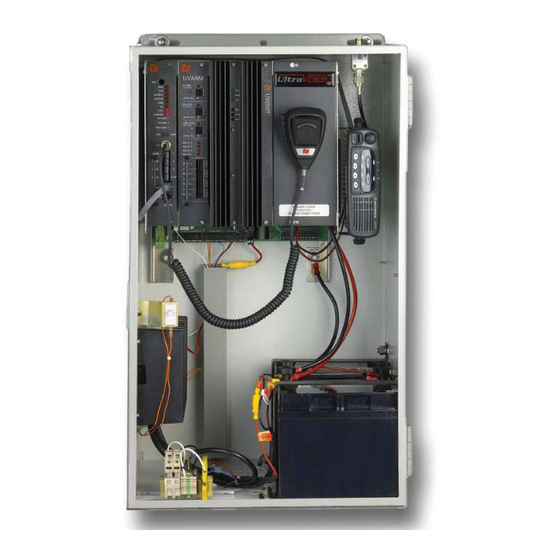
Page 23: Figure 2 Uvic Cabinet Dimensional Outline Drawing
Installation Figure 2 UVIC Cabinet Dimensional Outline Drawing Figure 3 UVIC Parts Layout Description, Specifications, Installation, Operation, and Service Manual... -
Page 24: General Mounting Guidelines For All Applications
Installation General Mounting Guidelines For All Applications These general installation instructions are pertinent to all installations. Specific mounting methods and required installation materials are described in the next section. 1. There are three pre-drilled holes in each of the cabinet mounting flanges. (See Figure 3 UVIC Cabinet Dimensional Outline Drawing.) Depending on the mounting surface, mount the cabinet using either of the following sets of holes: •... -
Page 25: Uvic Installation Material List And Installation Guidelines
Installation 6. After the cabinet is securely mounted, remove any debris that may have entered the cabinet. Remove the two battery hold-down brackets on the bottom right side of the enclosure. Install the batteries oriented as shown in Figure 5, but do not connect any wires to the batteries. -
Page 26: Concrete Or Filled Cement Block Wall Mounting Guidelines
Installation Material Description Purpose 1/2 inch Seal Tight Conduit and Electrical conduit from disconnect 5 in Fittings Metal Ground Bushings Equipment ground connections Screws, appropriate to mounting Disconnect mounting surface 15 A Breaker Service panel breaker serving unit White Wire appropriately sized AC neutral from breaker panel to disconnect Varies Black Wire appropriately sized AC load from breaker panel to disconnect... -
Page 27: Wood Stud Wall Mounting Guidelines
Installation Wood Stud Wall Mounting Guidelines Table 24 Wood Stud Wall Mounting Materials Material Description Purpose 3/8 x 3 in Lag bolts Backboard and cabinet mounting bolts 8 24 x 36 x 3/4 in Mounting backboard B/C or better plywood Construction adhesive Mounting backboard attachment 1. -
Page 28: Electrical Connections
Installation Electrical Connections Install the siren electrical system in compliance with local electrical codes and NEC recommendations. Federal Signal recommends that all user-installed conduit connections enter from the bottom of the UVIC cabinet using the supplied conduit knockouts. Disconnect all power and read all warnings at the beginning of this manual and on the batteries before making connections. -
Page 29: Wiring Guidelines For The 240 Vac Electrical Service
Installation 5. Connect the black line wire from the 15 A breaker to the DIN rail mounted terminal block labeled F2-Line in the UVIC cabinet. 6. Optionally, connect a green ground wire from the breaker panel earth ground to the green ground block in the UVIC cabinet or run a ground lead from the external 3/8 inch ground stud on the UVIC cabinet to earth ground. -
Page 30: Installing The Antenna
Installation 2. Open the fastener kit provided in the UVIC cabinet containing the plastic battery terminal knobs and spacer nuts. Replace the battery terminal bolts provided with the battery with the terminal knobs and nuts provided in the fastener kit. The kit also contains rubber bumpers that are placed under the battery holding brackets to better secure shorter batteries. -
Page 31: Pa Audio Connections (Jp15)
Installation The output voltage is 70 V for each of the amplifiers. You may connect up to 400 watts of speaker loads across the 70 V line for each amplifier. If multiple separate speaker wire runs must be used for the installation, use an external speaker wire junction box to simplify field wiring and limit the number of wires in the UVIC cabinet. -
Page 32: Contact Closure Inputs (Jp14)
Installation Contact Closure Inputs (JP14) Connect any desired remote contact closure inputs to the remote control inputs at JP14 on the Motherboard. See Specifications and Operations sections for further information on JP14. Optional UVARM Connections Connections to the UVARM are made on the front of the UVARM card located between the Control module and the Amplifiers. -
Page 33: External 24 Vdc Power Connections
Installation Figure 6 UVLOC Dimensional Outline Figure 7 UVLOC Interface Wiring Diagram External 24 VDC Power Connections If 24 Vdc battery power is required to run external devices, the UVIC has a large connector available labeled JP6 (-) 24 Vdc (+) located behind the cover plate on the right side of the amplifiers. -
Page 34: 600 Ohm I/O Connections
Installation The connector is rated for 50 A. The combined load of the UVIC and the external 24 Vdc load must not exceed 50 A. Wire gauge and fusing must be selected appropriately for the load. 600 Ohm I/O Connections Control Connections Use terminal block JP12 at the bottom of the system motherboard for making connections to 600 ohm balanced audio equipment (such as, a direct connection to a SS2000+ or other... -
Page 35: Figure 8 Uvic Strobe And Speaker Wiring
Installation Figure 8 UVIC Strobe and Speaker Wiring Description, Specifications, Installation, Operation, and Service Manual... -
Page 36: Installing User-Supplied Radio Receivers
Installation Installing User-Supplied Radio Receivers Improper installation of radio control equipment may cause the speakers to malfunction or operate intermittently. Installation must only be performed by experienced radio technicians who have thoroughly read this manual. 1. TUNING—Tune the radio receiver to the manufacturer’s specifications. 2. -
Page 37: Pre-Operational System Configuration And Testing
Pre-operational System Configuration and Testing Pre-operational System Configuration and Testing The following procedures should be performed by a properly trained technician to ensure the equipment is operating properly. Visual Inspection To conduct a visual inspection: 1. Fill out the Field Test Data Sheet to document the following inspections and tests. See Appendix A. -
Page 38: Adjusting The Radio Transceiver
Pre-operational System Configuration and Testing Adjusting the Radio Transceiver This procedure is previously completed at factory. Only readjust if radio re-alignment is required or if the radio is being installed in the field. Qualifications Requires a properly trained Radio Technician. Equipment Required •... -
Page 39: 600 Ohm Level Adjustment Procedure For Communications
Pre-operational System Configuration and Testing Set all sites in the system to the same modulation level. 600 Ohm Level Adjustment Procedure for Communications To use the 600 ohm input for receive audio, a jumper must be across pins 2-3 of JP8. JP8 is located internally on the main controller card. -
Page 40: Control And Status Monitoring
Pre-operational System Configuration and Testing Set for same level as the standard siren sounds. d. Ensure that the sound is not distorted. Control and Status Monitoring To test the control and status monitoring features: 1. Use the Commander Software System to verify the UVIC has been properly configured for the application. -
Page 41: Operations
Operations Operations The UVIC is housed in a cabinet that contains a card cage with four plug-in cards consisting of the following: • One controller slot • One optional accessory slot • Two amplifier slots UV Controller and UV400 Amplifier Front Panel Indicators The following table provides the descriptions of the front panel indicators. -
Page 42: Basic Uvic Controller Programming
Operations Label Description OVER TEMP Over Temperature LED is on when amplifier reaches an over- temperature condition. Call Technical Support if light remains LIMITED Power Limiting is on or flashing during activation when overdriving amplifier. SHORT Shorted Load is on when load appears shorted. Figure 9 UV Controller and UV400 Amplifier Front Panel Indicators ANTENNA CONNECTOR RS232 RECEIVE LED... -
Page 43: Radio Communications
Operations Table 30 Unit Type Selection Table Unit type Quantity Siren Type Total Power UV - 1 One (1) UV400 MOD1004B 400 W UV - 2 Two (2) UV400 MOD2008B 800 W This section contains reference drawings to assist with installation. Radio Communications For units equipped with the integral radio receiver, the RF frequency configuration parameter sets the frequency of the radio channel. -
Page 44: User Programs
Operations User Programs The UVIC controller has the capacity to store up to fifty user programs. Each user program contains twenty stacked function items. Assigning more than one function to each activation code or user program allows you to run a sequence of functions without sending additional activation commands. Activation Functions Table 31 Activation Functions Function... -
Page 45: Site Address Switch (S1)
Operations Function Definition Low Power/ Causes the siren to operate at a greatly reduced volume level. Upon High Power activation of a user program, the siren defaults to High (normal) volume level. This command must follow an ARM command. Reduced volume mode remains in effect for all subsequent functions in a user program that follow the Low Power function or until a High Power function occurs or an ARM command is sent. -
Page 46: Figure 10 Setting The Switch Number Example
Operations 1, 2, 4, 8, 16, 32, 64, 128 256, 512. Add appropriate dip switch values to define the site number address. Example To define the board for Site #1 toggle first dip switch to the left. All other dip switches are to the right. -
Page 47: Connectors And Indicators For The Uvarm
Operations Connectors and Indicators for the UVARM Table 32 Connectors for the UVARM Wire Size All front panel connectors 22 to 14 AWG Back plane 48 pin EPT male card edge connector 33 ohm audio output 1 and 2 balanced output 600 ohm audio output 1 and 2 balanced output 600 ohm/line level audio output... -
Page 48: Connectors And Indicators For The Serial To Network Pcb
Operations Figure 11 UVARM Identification Connectors and Indicators for the Serial to Network PCB Table 34 Connectors for the Serial to Network PCB 600 Ohm Audio Output Port Balanced line output (To JP12 UVIC motherboard) 10.5-95 Vdc Power Input 1- (-) 2- (+) Resets board back to factory default settings. -
Page 49: Connectors For The Front Panel
To Serial Interface +12V Input Power CONFIG/FLASH Federal Signal Corporation Copyright 2006 2005457_ 291351A Connectors for the Front Panel The following table provides settings and interface inputs and outputs for the UV+ controller card. Table 36 UV+ Controller Card Setting I/O... -
Page 50: Connectors, Indicators, And Fuses For The Backplane Motherboard
Operations 600 ohm Input Configuration Jumper Pins: Use shorting plug between pins 2 and 3 600 ohm audio in to receiver decoders Use shorting plug between pins 1 and 2 Audio from 600 ohm to go to amplifiers when 600 ohm PTT is closed 600 ohm Output Configuration Jumper Pins: Use shorting plug between pins 1 and 2... - Page 51 Operations JP13 Filtered 24 Vdc Power Output Pin 1 Ground Pin 2 +24 Vdc JP14 Remote Activation Input Pins: 1,10 ISO Ground 2 Function 1 3 Function 2 4 Function 3 5 Function 4 6 Function 5 7 Function 6 8 Function 7 9 Function 8 JP15...
-
Page 52: Table 38 Fuses For The Backplane Motherboard
Operations JP20 Charger Sensor Input Pins: 1,3 Ground 2 Input from Charger - See JP4 on controller board JP21 Amplifier 1 Output Pins: 1 - 12 SIG - JP22 Amplifier 1 Output Pins: 1 - 12 SIG + JP23 Amplifier 2 Output Pins: 1 - 12 SIG - JP24... -
Page 53: Table 39 Motherboard Outline Drawing
Operations Table 39 Motherboard Outline Drawing Description, Specifications, Installation, Operation, and Service Manual... -
Page 54: Manual Activation
Operations Manual Activation Use the manual activation switches to activate siren functions. Switches are located on the face of the controller. In addition, activating switches simultaneously can operate specific testing and calibration features. See Table 40. Figure 13 UV+ Controller Card Switches Table 40 Manual Activation Switches on UV+ Controller Card Function Switch Function... -
Page 55: Relay Output (Jp11)
Operations NOTE: • The microphone volume adjustment knob, labeled MIC GAIN, is located on controller card front panel. • Local PA overrides ALL siren functions activated either remotely or locally. Relay Output (JP11) The relay output is terminal block JP11, which is located at the bottom of the backplane motherboard. -
Page 56: Sensor Inputs (Jp15)
Operations Table 41 Remote Activation Connections (JP14) JP14 Terminal Function 1—COM Common 2—F1 F1—Activates functions 1 3—F2 F2—Activates functions 2 4—F3 F3—Activates functions 3 5—F4 F4—Activates functions 4 6—F5 F5—Activates functions 5 7—F6 F6—Activates functions 6 8—F7 F7—Activates functions 7 9—F8 F8—Activates functions 8 10—COM... -
Page 57: Vdc Supply (Jp16)
Operations AC Power/Solar (JP15: pins 7 and 8) Jumper JP15 pins 7 and 8 when using solar only. If using ac, 7 and 8 are connected to ac power sensor. 600 ohm PTT (JP15: pins 9 and 10) Shorting pins 9 and 10 puts the UV+ controller card in local PA mode. User-Defined Application (JP15: pins 11 and 12) Use spare JP15: pins 11 and 12 for user-defined application. -
Page 58: Local Quiet Test
Operations Local Quiet Test The Local Quiet test allows performing Quiet Tests on the siren control and siren speaker array. Quiet Test uses a 20 kHz tone to quietly test the tone generators, amplifiers, and speaker drivers. To perform this test, program the Quiet Test under one of the activation codes. -
Page 59: Uvloc
Operations Figure 15 LEDs on charger Table 44 LEDs description Description CURRENT Green LED indicates charge current is being delivered to the battery. LED intensity increases with charge current. TRICKLE Yellow LED indicates battery voltage is below 20 V and the charger is trickle charging at a low current level. -
Page 60: Activating A Digital Voice Message
Operations When the ACTIVATE button is released, the microphone is disconnected and the function stops until the ACTIVATE button is pressed again. Figure 16 Using UVLOC Controls Activating a Digital Voice Message To activate a digital voice message: 1. Press the ARM switch for 1 second. 2. -
Page 61: Figure 17 Uvloc Drawing
Operations Figure 17 UVLOC Drawing Description, Specifications, Installation, Operation, and Service Manual... -
Page 62: Maintenance
Maintenance Maintenance Service and maintenance should be performed by qualified personnel familiar with the UVIC, associated controls, and power sources being used and in conjunction with the authorities having jurisdiction. The sound output of speakers is capable of causing permanent hearing damage. -
Page 63: Replacement Parts
Replacement Parts For the 860000236-01 charger: The voltage of a fully charged set of batteries should be approximately 27.0 VDC, and charger current should be less than 2 amperes. The charger is set for 27.0 +/- 0.1 VDC at room temperature. 2. -
Page 64: Getting Service
Getting Service Getting Service If you are experiencing any difficulties, contact Federal Signal Customer Support at: 800-548-7229 or 708-534-3400 extension 7511 or Technical Support at: 800-524-3021 or 708-534-3400 extension 7329 or through e-mail at: techsupport@fedsig.com. For instruction manuals and information on related products, visit: http://www.fedsig.com/ UltraVoice Indoor Controller (UVIC) -
Page 65: Appendix A Icm-Uv Checklist
Appendix A ICM-UV Checklist Appendix A ICM-UV Checklist Type of service performed: Install Commissioning Maintenance Project Information Customer Name: FS Order #: Installation Company: Tech: Contact #: Siren Information (complete this section for install, commissioning & maintenance) Siren Controller Type: Site # Siren Head Type: S/N:... - Page 66 Appendix A ICM-UV Checklist Speaker Impedance > 4.0 Ohm Amplifier RMS VAC Amplifier RMS If more than 8 amps, use identical 2nd form Speakers Disconnected VAC Speakers Connected Amp 1: Ohms • Typically, 4.7 Ohms for Amp 1: Amp 1: a MOD Amp 2: Ohms...
-
Page 67: Appendix B Drawings
Appendix B Drawings Figure 18 UVIC Wiring Diagram... -
Page 68: Figure 19 Uvic-Ip Wiring Diagram
Figure 19 UVIC-IP Wiring Diagram... -
Page 69: Figure 20 Uvic-Ll Wiring Diagram
Figure 20 UVIC-LL Wiring Diagram... -
Page 70: Figure 21 Uvic Final Assembly And Parts List
2645 FEDERAL SIGNAL DRIVE - UNIVERSITY PARK,IL 60466 SEE ECR #9210 FINISH: 2/23/18 MATERIAL DESCRIBED AND INFORMATION CONVEYED IS PROPRIETARY TO FEDERAL SIGNAL CORPORATION, IS SEE ECR #8484 10/12/17 OR MAY BE THE SUBJECT OF PATENT APPLICATIONS, AND MAY OR MAYNOT BE COPIED, DIVULGED TO OTHERS,...
Need help?
Do you have a question about the UltraVoice UVIC and is the answer not in the manual?
Questions and answers