
Related Manuals for Federal Signal Corporation UltraVoice UVRI-B Series


Summary of Contents for Federal Signal Corporation UltraVoice UVRI-B Series
- Page 1 UltraVoice Remote Interface ® Indoor Controller Model: UVRI-B Description, Specifications, Installation, and Operation Manual 25500444 Rev. A7 0120 Printed in U.S.A. © Copyright 2018-2020 Federal Signal Corporation...
- Page 2 A copy of this limited warranty can also be obtained by written request to Federal Signal Corporation, 2645 Federal Signal Drive, University Park, IL 60484, email to info@fedsig.com or call +1 708-534-3400.
-
Page 3: Table Of Contents
Contents Safety Messages..............................8 General Description ..............................10 Overview ................................10 Features ................................10 Ordering Information ..........................11 Specifications ................................12 Installation ................................16 Control Unit Location ............................16 General Mounting Guidelines ...........................22 UVRI-B Installation Material List and Installation Guidelines ................22 Concrete or Filled Cement Block Wall Mounting Guidelines ..............22 Hollow Block Wall Mounting Guidelines ....................23 Wood Stud Wall Mounting Guidelines .......................23 Metal Stud Wall Mounting Guidelines .......................23... - Page 4 Terminating Unused Inputs and Outputs....................30 Turning on the Power ............................32 Installing the Antenna ............................32 Installing the Cabinet Mounted Magnetic Base Antenna ................32 Installing the Remote Mounted Magnetic Base Antenna ................32 Pre-operational System Configuration and Testing ...................33 Visual Inspection ...............................33 Amplifier and Speaker Pre-Operation Checkout ....................33 Adjusting the Radio Transceiver (if applicable) ....................33 Control and Status Monitoring ..........................34 Operations................................35...
- Page 5 Manual Activation ..............................48 Local Public Address ............................48 Relay Output ..............................49 Sensor Inputs ..............................49 Status Monitoring ..............................50 Quiet Test ................................50 AC/DC Power System ............................50 Restoring Configuration to Factory Defaults .....................50 Applications ................................50 Two-Way Radio Controlled System ........................50 Fire Panel Interface ............................51 Fiber-connected Facility ............................51 Maintenance ................................51 Control Unit Preventive Maintenance .......................51...
- Page 6 Tables Table 1 Ordering Information ..........................11 Table 2 Accessories ..............................12 Table 3 Electrical on the Control Board ......................12 Table 4 Electrical on the Amplifier Board ......................12 Table 5 Serial and I C Ports on Control Board ....................13 Table 6 Relay Outputs on Control Board ......................13 Table 7 600 ohm I/O Balanced Line on Control Board ..................13 Table 8 Audio Outputs on Control Board ......................13 Table 9 Audio Sense Input on Control Board .....................13...
- Page 7 Table 26 Indicators on the Amplifier Board ......................44 Table 27 POT Settings on the Control Board ......................45 Table 28 POT Settings on the Amplifier Board ....................45 Table 29 Software Tests ............................45 Table 30 Manual Activation Buttons on Control Board ..................48 Table 31 Sensor Connections ..........................49 Table 32 Troubleshooting .............................53 Table 33 Replacement Part Numbers ........................53...
-
Page 8: Safety Messages
Safety Messages Safety Messages It is important to follow all instructions shipped with this product. This device is to be installed by trained personnel who are thoroughly familiar with the country electric codes and will follow these guidelines as well as local codes and ordinances, including any state or local noise control ordinances. - Page 9 Safety Messages • After installation, service, or maintenance, test the siren system to confirm that it is operating properly. Test the system regularly to confirm that it will be operational in an emergency. • If future service and operating personnel do not have these instructions to refer to, the siren system may not provide the intended audible warning and service personnel may be exposed to death, permanent hearing loss, or other bodily injury.
-
Page 10: General Description
General Description General Description Overview The UltraVoice Remote Interface unit (UVRI-B) provides remote extension of Federal Signal indoor and outdoor warning systems. The UVRI-B is available for indoor applications only. The UVRI-B is available with a number of standard and optional features to allow efficient and cost-effective alerting and notification. -
Page 11: Ordering Information
General Description • Remote monitoring of system and speaker circuits • Optional cellular, satellite, or broadband IP communications • Stackable siren functions enable user pre-defined warning scenarios • 600-ohm I/O for wire line control and status monitoring • 600-ohm input/output for connection to external amplifiers and fire protection systems •... -
Page 12: Specifications
Specifications Table 2 Accessories Model Description X-SM1-FS1 Ambient Noise Microphone MNC-MC Noise Canceling Push to Talk Microphone Specifications Table 3 Electrical on the Control Board AC Power (JP38) 102-132 Vac, 120 VAC nominal, -15%, +10% < 150 mA Standby < 200 mA with active with NO amplifier and NO radio <... -
Page 13: Table 5 Serial And I
Specifications Table 5 Serial and I C Ports on Control Board Serial Port Protocol RS232C 115200,N,8,1 C Port Protocol Philips Standard I Table 6 Relay Outputs on Control Board Quantity Contact Rating 10 A, 250 Vac, 30 Vdc, Optically isolated, (NO and NC) Table 7 600 ohm I/O Balanced Line on Control Board Audio Input Level Minimum of 0.10 to at least 2 V... -
Page 14: Table 11 Tc1 Relay Outputs On Control Board
Specifications Table 11 TC1 Relay Outputs on Control Board Quantity 4, incorporating 4.75 KΩ EOL resistive load Open loop; Current < 220 µA / pull-up Voltage < 1.3 V. Shorted loop; < 1.10 V (Out- to Out+). Ground Fault, Earth ground to; <... -
Page 15: Table 14 Environmental And Physical
Specifications DTMF All timings in milliseconds String length 3-12 standard DTMF characters Mark/Space timing: Decoder Minimum 50 ms/50 ms (below 50/50 consult factory) Decoder Maximum 800 ms total mark/space timing per code Encoder 100 ms/100 ms mark/space timing Space between Stacked codes minimum 1.25 seconds AFSK Baud rate... -
Page 16: Installation
Installation Installation ELECTROCUTION HAZARD: Electrocution or severe personal injury can occur when making electrical connections, drilling holes, or lifting equipment. Therefore, experienced electricians, in accordance with national and local electrical codes, acting under the direction of the installation crew safety foreman, should perform installation. -
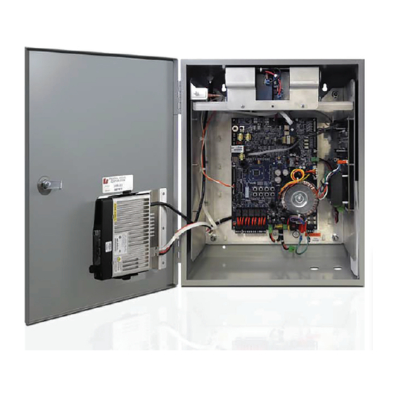
Page 17: Figure 1 Uvri-B Parts Layout
Installation Installation Figure 1 UVRI-B Parts Layout Figure 1 UVRI-B Parts Layout FAULT TYPE N - FEMALE INDICATOR ANTENNA CONNECTOR 12VDC BATTERY INTRUSION SWITCH MICROPHONE CLIP (OPTIONAL) CONTROL PCBA AUDIO AMPLIFIER PCBA AMPLIFIER AUDIO OUTPUT SPEAKER RELAY AC POWER CONNECTIONS INPUT TRANSCEIVER (OPTIONAL) -
Page 18: Figure 2 Typical Uvri-B Installation Drawing (Fire Panel Interface)
Installation Figure 2 Typical UVRI-B Installation Drawing (Fire Panel Interface) Distributed Speakers Transceiver Antenna (External antenna requires lightning protection) LMR400 Antenna Cable Antenna Ground Required for Outdoor Antenna Masts Type N Female Bulkhead Connector Fused AC Service Disconnect Remote Fire UVRI-B Alarm / PA System... -
Page 19: Figure 3 Uvri-B Cabinet Dimensional - Front And Side View
Installation Figure 3 UVRI-B Cabinet Dimensional - Front and Side View 1.50" 1.82" 6.62" 20.00" 20.36" 16.30" 6X 1/2" CONDUIT KNOCKOUTS 3.34" 2.50" 1.74" 16.00" Description, Specifications, Installation, and Operation Manual Federal Signal www.fedsig.com... -
Page 20: Figure 4 Uvri-B Cabinet Dimensional - Back View
Installation Figure 4 UVRI-B Cabinet Dimensional - Back View 2X R.16 0.44" 2X R.25 17.88" 2X .31 11.00" UltraVoice Remote Interface (UVRI-B) Federal Signal www.fedsig.com... -
Page 21: Figure 5 Uvri-B Wiring Diagram
Installation Figure 5 UVRI-B Wiring Diagram Description, Specifications, Installation, and Operation Manual Federal Signal www.fedsig.com... -
Page 22: General Mounting Guidelines
Installation General Mounting Guidelines Use good installation methods and follow local ordinances for mounting cabinet. These general installation instructions are pertinent to all installations. Specific mounting methods and required installation materials are described in the next section. There are two keyhole type slots and two pre-drilled holes for mounting, located on the back panel of the cabinet. -
Page 23: Hollow Block Wall Mounting Guidelines
Installation structural integrity. Hollow Block Wall Mounting Guidelines Table 16 Hollow Block Wall Mounting Materials Material Description Purpose 1/4 in x 2 in Heavy Duty Toggle Bolts Anchor Bolts Mark the mounting hole locations on the wall for the cabinet. Install the anchor bolts for the four cabinet corners according to the manufacturer’s instructions. -
Page 24: Electrical Connections
Installation Apply construction adhesive to the back of the mounting backboard. Attach the mounting backboard to the wall with #14 metal stud screws. 5. Locate the mounting position of the cabinet on the mounting backboard. 6. Drill pilot holes for the 1/4-inch lag bolts. Mount the cabinet to the mounting backboard. -
Page 25: Grounding Requirements
Installation Grounding Requirements Review the following grounding requirements: • The UVRI-B cabinet must be properly connected to an earth ground. The cabinet contains an internal ground stud for making this connection. • If an outdoor antenna is used, install a separate antenna ground. •... -
Page 26: Connecting Audio Output
Installation 5. Connect the black line wire from the 15 A breaker to pin 3 of JP38, L1/HOT, on the UVRI-B control board. 6. Connect a green ground wire from the breaker panel earth ground to the ground stud in the UVRI-B cabinet and to pin 1 of JP38, GND, on the UVRI-B control board. To avoid shorting the output of the charger, do not apply AC power to the UVRI-B controller before making the battery connections described later in this section. -
Page 27: Local Pa Audio Connections (J1 On The Uvri-B Control Board)
Installation Local PA Audio Connections (J1 on the UVRI-B Control board) For local PA, plug the optional microphone (part number: MNC-MC) into the 1/4 inch jack (J1) on the UVRI-B control board. Mount the microphone on the microphone clip located on the access panel. -
Page 28: Audio Connections
Installation Use a twisted pair wire run to the connecting equipment which should have a balanced 600 ohm output. Keep the cable length as short as possible and run away from sources of electrical noise. The input works best with an input level between 200 to 2,000 mV . -
Page 29: Figure 6 Tc Inputs And Ouputs With Fire Panel
Installation Figure 6 TC Inputs and Ouputs with Fire Panel Description, Specifications, Installation, and Operation Manual Federal Signal www.fedsig.com... -
Page 30: Terminating Unused Inputs And Outputs
Installation Terminating Unused Inputs and Outputs Unused inputs and outputs must be terminated. To terminate unused inputs and outputs: Connect the unused inputs to the unused outputs using a 1 kΩ and 2.2 kΩ resistor as shown in Figure 7. Connect the commons together. -
Page 31: Figure 7 Terminating Unused Tc Inputs And Outputs
Installation Figure 7 Terminating Unused TC Inputs and Outputs Description, Specifications, Installation, and Operation Manual Federal Signal www.fedsig.com... -
Page 32: Turning On The Power
Installing the Antenna Turning on the Power To turn the power on: Verify all wiring is completed in the previous sections and that the connections are tight and secure. Connect the battery supply wires to the control board with the pluggable connector at JP36. -
Page 33: Pre-Operational System Configuration And Testing
Pre-operational System Configuration and Testing Pre-operational System Configuration and Testing The following procedures should be performed by a properly trained technician to ensure the equipment is operating properly. Visual Inspection To conduct a visual inspection: Fill out the ICM-UV Checklist to document the following inspections and tests. See Appendix A. -
Page 34: Control And Status Monitoring
Pre-operational System Configuration and Testing Equipment Required • Service Monitor • Oscilloscope Setup Connect the radio to the service monitor. Receive Audio Adjustment To receive audio adjustment: Using service monitor, modulate the correct RF signal into the receiver with a 1 kHz tone at 3 kHz deviation. -
Page 35: Operations
Operations Operations Communications Link When the UVRI-B is equipped with a communications interface, the following interface parameters require configuration: Unit Type, RF Frequency, Security Key, 128/256-bit Encryption Key, Site Address, and Configuration Jumper Settings. Unit Type The Federal Signal Commander System requires configuration based on the communications method. -
Page 36: Figure 8 Setting The Switch Number Example
Operations Figure 8 Setting the Switch Number Example Switch number Binary number Example: Switch numbers 1, 2, and 3 are binary numbers 1, 2, and 4. Add 1 + 2 + 4 = 7; 7 is the unit address NOTES: •... -
Page 37: User Programs
Operations User Programs The UVRI-B has the capacity to store functions for specific alerting configuration. Use functions to activate relays for control of external devices and activation of pre-recorded messages. See the Commander Software Manual and the Informer-IP Setup, Program, and User Manual. - Page 38 Operations JP14 TC1 Interface/Spare Inputs (Typically used for fire panel interface) Isolated (-) TC2-1 / Spare #3 Request to activate audio, ready Isolated (-) TC2-2 / Spare #4 Request to manage evacuation signals, ready Isolated (-) TC2-3 / Spare #5 Request to manage visible alert signals, ready Isolated (-) TC2-4 / Spare #6 Trouble condition JP18...
- Page 39 Operations JP33 Rotation Relay Output Common Normally Open Normally Closed JP34 Relay Outputs Relay # 1 Common Relay # 1 Normally Open Relay # 1 Normally Closed Relay # 2 Common Relay # 2 Normally Open Relay # 2 Normally Closed Relay # 3 Common Relay # 3 Normally Open Relay # 3 Normally Closed...
-
Page 40: Figure 9 Uvri-B Boards (Lines A, B, C For Control Board To Amplifier Connection)
Operations Figure 9 UVRI-B Boards (Lines A, B, C for Control Board to Amplifier Connection) UV Amplifier Board Speaker Output (JP2) Input Level 20 Amp (F1) Line C Audio Input (JP3) DC Power Audio Output Input (JP8) (JP9) C (JP5) Line A 10/25 V Audio Output Control Board... -
Page 41: Figure 10 Control Board With Configuration Jumpers, Controls, And Indicators
Operations Figure 10 Control Board with Configuration Jumpers, Controls, and indicators JP39 D9 D10 JP14 JP13 JP2 JP3 JP11 JP12 JP10 JP16 JP18 JP17 JP15 R103 R141 JP20 (DV GAIN POT) JP41 JP19 JP31 D40, D41, D42 JP7 JP42 JP21 JP40 JP43 JP23... -
Page 42: Configuration Jumpers
Operations Table 21 Connectors on the Amplifier Board (See Figure 9) Speaker Output 1 To Control board JP34 1 and 4 2 To Speaker Common JP3 (Line C) Balanced Audio Line Input 1 and 2 1.33 to 10/25 V Audio Output (JP6) on the Control board Audio Input Level Select 1 and 2 –... -
Page 43: Table 23 Configuration Jumpers On The Amplifier Board
Operations JP27 Options Connector: Microcontroller Input Ground JP40 Options Jumper - future use JP44 Short to enable Sounder/Piezo JP45 Battery charger current limit: 1.5 A un-jumpered, 4 A jumpered Table 23 Configuration Jumpers on the Amplifier Board Audio Input Level Select 1 and 2 –... -
Page 44: Indicators
Operations Indicators Table 25 Indicators on the Control Board (See Figure 10) TC Interface GND Fault TC Interface Line Fault TC Interface TC2-4 / Spare #6 Input TC Interface TC2-1 / Spare #3 Input TC Interface TC2-2 / Spare #4 Input TC Interface TC2-3 / Spare #5 Input TC Interface TC1-2 Output TC Interface TC1-3 Output... -
Page 45: Pot Settings
Operations POT Settings Table 27 POT Settings on the Control Board Output level for 10 V/25 V and 8 Ω, 0.7 W Audio outputs, (Default = Turn clockwise 20 turns or all of the way up.) R103 Digital Voice Gain, (Default = Turn clockwise 20 turns or all of the way up.) Table 28 POT Settings on the Amplifier Board Volume Control,... -
Page 46: Digital Voice Recording
Operations Digital Voice Recording When purchased, the Digital Voice option adds a microSD card that is capable of storing up to 4,093 voice or tone messages that total up to 17 hours of total recording time. File Format The digital voice message format is 8000 samples per second, 8 bit, mono. Save these messages with a DV#.wav naming format or the messages are not recognized. -
Page 47: Converting The Files
Operations Alternatively, with the speakers plugged into the amplifiers: Turn the DV GAIN pot fully (25 turns) counter clockwise. Play the stored tone function. Monitor the amplifiers output level. Turn up the DV GAIN pot until 23 V is reached. NOTE: It is important to start by turning the DV GAIN pot down to a low level and work your way up to prevent overdriving the amplifiers and speakers. -
Page 48: Manual Activation
Manual Activation If configured, use the manual activation switches to activate siren functions. Buttons are located on the Control Board. Figure 11 UVRI-B Activation Buttons Table 30 Manual Activation Buttons on Control Board Function Switch Function Code # 1 Activation Switch Code # 5 Activation Switch Code # 6 Activation Switch Code # 2 Activation Switch... -
Page 49: Relay Output
Operations Relay Output The UVRI-B provides five high-powered relays for control of external hardware. Sensor Inputs Terminal block JP24 is located on the left edge of the UVRI-B control board. Use sensor inputs to detect and notify conditions occurring at an RTU location. Table 31 Sensor Connections JP24 Terminal Function... -
Page 50: Status Monitoring
Applications Status Monitoring The UVRI-B uses a variety of sensors to communicate its status back to the Federal Signal Commander System. This alerts personnel of potential issues at the UVRI-B unit. The UVRI-B monitors power, battery, door opening, amplifier status and other important system components. -
Page 51: Fire Panel Interface
Maintenance Fire Panel Interface The UVRI-B is designed to interface with a UL2572 fire panel for control, monitoring, and activation of a Mass Notification System. Use the UVRI-B in military, industrial, and campus environments where interfacing Federal Signal outdoor warning into a fire panel is required. -
Page 52: General Maintenance
Maintenance General Maintenance Checking Signal Operational To check signal operation: When checking for proper control module output, unplug the terminal strip connector to the speakers to eliminate output from the speaker array. Activate each of the signals and observe the signal indicators on the control module and the amplifiers. -
Page 53: Troubleshooting
Troubleshooting Remove the battery bracket and then remove the battery. 5. Reassemble in the reverse order of these steps. Troubleshooting Table 32 Troubleshooting Problem Action No Radio Decode • Unit is not programmed to recognize that particular code sequence or signal is not being received properly. •... -
Page 54: Getting Service
Getting Service Getting Service If you are experiencing any difficulties, contact Federal Signal Customer Support at 800-548-7229 or 708-534-3400 extension 7511 or Technical Support at 800-524-3021 or 708-534-3400 extension 7329 or through e-mail at techsupport@fedsig.com. For instruction manuals and information on related products, visit http://www.fedsig.com/ UltraVoice Remote Interface (UVRI-B) Federal Signal www.fedsig.com... -
Page 55: Appendix A Icm-Uv Checklist
Appendix A ICM-UV Checklist Appendix A ICM-UV Checklist Type of service performed: Install Commissioning Maintenance Project Information Customer Name: FS Order #: Installation Company: Tech: Contact #: Siren Information (complete this section for install, commissioning & maintenance) Siren Controller Type: Site # Siren Head Type: S/N:... - Page 56 Appendix A ICM-UV Checklist Speaker Impedance > 4.0 ohms Amplifier RMS VAC Amplifier RMS If more than 8 amps, use identical 2nd form Speakers Disconnected VAC Speakers Connected Amp 1: ohms • Typically, 4.7 ohms for Amp 1: Amp 1: a MOD Amp 2: ohms...
Need help?
Do you have a question about the UltraVoice UVRI-B Series and is the answer not in the manual?
Questions and answers