Table of Contents
Advertisement
2562118D REV. D1 0420
Safety Message to Installers and Service Personnel of Warning Light Equipment
People's lives depend on your proper installation and servicing of Federal Signal products. It is important
to read and follow all instructions shipped with this product and the original product. Listed below are
some other important safety instructions and precautions you should follow:
• To properly install this device, you must have a good understanding of automotive electrical
procedures and systems, along with proficiency in the installation and use of safety warning
equipment.
• DO NOT install equipment or route wiring in the deployment path of an airbag.
• If a vehicle seat is temporarily removed, verify with the vehicle manufacturer if the seat needs to be
recalibrated for proper airbag deployment.
• When drilling into a vehicle structure, ensure that both sides of the surface are clear of anything that
could be damaged.
• In order for the device to function properly, a good ground connection must be made. At a minimum,
it must be attached to a solid metal body or chassis part that will provide an effective ground path as
long as the light system is to be used.
• Locate light control so the VEHICLE and CONTROL can be operated safely under all driving
conditions.
• Do not attempt to activate or deactivate light control while driving in a hazardous situation.
• This product controls high intensity lighting devices. To prevent eye damage, DO NOT stare into the
light beam at close range.
• Frequently inspect the light to ensure that it is operating properly and that it is securely attached to
the vehicle.
• File these instructions in a safe place and refer to them when maintaining and/or reinstalling the
product.
• Failure to follow all safety precautions and instructions may result in property damage, serious injury, or
death.
Overview
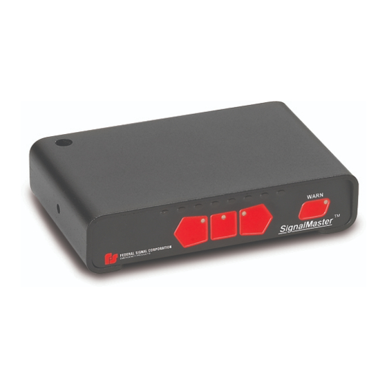
The Model 330104 SMC1 is a directional light controller. It is designed to operate the full selection of
Federal Signal SignalMaster directional light bars from four to eight light heads, either continuous or split,
at 12 V or 24 V. The control circuitry is protected against reverse polarity by a 2 A fuse and a diode. The
light bar requires its own appropriately sized fuse.
This model provides six distinctive directional signals. There are standard left-arrow, center-out, and
right-arrow patterns as well as special left-arrow, center-out, and right-arrow patterns that comply with
CAC Title 13, Article 22 if used with the appropriate SignalMaster directional light bar in Tables 1 and 2 on
page 2.
Instructions for the Model 330104 SMC1
SignalMaster
Light Bar Controller
™
Advertisement
Table of Contents

Related Manuals for Federal Signal Corporation SignalMaster 330104 SMC1


Summary of Contents for Federal Signal Corporation SignalMaster 330104 SMC1
- Page 1 Instructions for the Model 330104 SMC1 SignalMaster Light Bar Controller ™ 2562118D REV. D1 0420 Safety Message to Installers and Service Personnel of Warning Light Equipment People’s lives depend on your proper installation and servicing of Federal Signal products. It is important to read and follow all instructions shipped with this product and the original product.
- Page 2 Installation and Programming Instructions Table 1 Halogen SignalMaster directional warning lights ™ (for CAC Title 13, Article 22 compliance) Model Length Lamps Cable Lenses 320142 20 in 30 ft Amber 320162 31 in 15 ft Amber 320612 31 in 30 ft Amber 320172 42 in...
- Page 3 Installation and Programming Instructions Table 3 Model 330104 Controller Specifications Electrical Input Voltage 11 Vdc to 28 Vdc Polarity Negative ground only Operating Temperature Range -30°C to +65°C Standby Current 7 mA (0.007 A) Light Bar Fuse 20 A, installer-provided +IGNITION Fuse Output Drive Capability (Total) Eight 27 W lamps on eight channels...
-
Page 4: Connecting Power To The Controller
Installation and Programming Instructions DRILLING PRECAUTIONS: When drilling holes, check the area into which you are drilling to ensure that you do not damage vehicle components. All drilled holes should be deburred and all sharp edges should be smoothed. All wire routing going through drilled holes should be pro- tected by a grommet or convolute/split-loom weaving. - Page 5 Installation and Programming Instructions BATTERY EXPLOSION: To avoid a battery explosion, always disconnect the negative battery cable first and reconnect it last. Avoid causing a spark when connecting near or to the battery. The gases produced by a battery can cause a battery explosion that could result in vehicle damage and serious injury.
-
Page 6: Mounting The Controller
Installation and Programming Instructions Wiring the Six- and Eight-Head SignalMaster ™ To wire the SignalMaster: 1. Connect the colored wires from the nine-conductor cable to the locations specified in Figure 2 or on the label affixed to the controller housing. NOTE: With the six-head SignalMaster light bar, the white and blue wires are not needed and can be cut even with the cable sheath. -
Page 7: Configuring The Controller
Installation and Programming Instructions 3. Angle the controller for optimum visibility from the operator’s position before tightening the screws. 4. Dress the cables and wires, and secure them out of the way. Configuring the Controller The controller has several installer-selectable warning patterns that you can select after the installation and wiring of the SignalMaster system is complete. -
Page 8: Entering Program Mode
Installation and Programming Instructions Table 7 Warn patterns compliant with CAC Title 13, Article 22 Pattern Description Null (no pattern) Alternating, two-head flash on each end Alternating in/out Alternating odds/evens Entering Program Mode With the vehicle ignition turned on and the directional light turned off, press the LEFT ARROW and CENTER OUT buttons simultaneously. - Page 9 Installation and Programming Instructions Safety Message to Operators of Warning Light Equipment Peoples’ lives depend on your safe use of our products. Listed below are some important safety instructions and precautions you should follow: • Do not attempt to activate or de-activate the light system control while driving in a hazardous situation.
-
Page 10: Testing The Installation
This product is subject to and covered by a limited warranty, a copy of which can be found at www.fedsig.com/SSG-Warranty. A copy of this limited warranty can also be obtained by written request to Federal Signal Corporation, 2645 Federal Signal Drive, University Park, IL 60484, email to info@fedsig. com or call +1 708-534-3400. -
Page 11: Ordering Replacement Parts
Installation and Programming Instructions Ordering Replacement Parts To order replacement parts, call Customer Support at 1-800-264-3578, 7 a.m. to 5 p.m., Monday through Friday (CT) or contact your nearest distributor. Table 8 Replacement Parts Qty. Description Part No. Controller 330104 Terminal Spade. - Page 12 2645 Federal Signal Drive University Park, Illinois 60484-3167 www.fedsig.com Customer Support Police/Fire-EMS: 800-264-3578 • +1 708 534-3400 Work Truck: 800-824-0254 • +1 708 534-3400 Technical Support: 800-433-9132 • +1 708 534-3400 © Copyright 1994-2020 Federal Signal Corporation...
Need help?
Do you have a question about the SignalMaster 330104 SMC1 and is the answer not in the manual?
Questions and answers