
Related Manuals for Lowenstein Medical prisma VENT AQUA 100506


Summary of Contents for Lowenstein Medical prisma VENT AQUA 100506
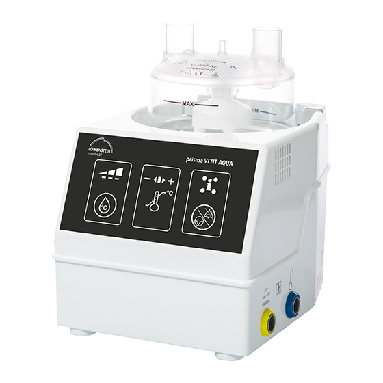
- Page 1 prisma VENT AQUA respiratory humidifier Instructions for use and technical description...
-
Page 2: Table Of Contents
Contents Scope of use ........................4 Warnings, Cautions and Guidelines ................5 Warnings ......................5 Precautions ......................7 Guidelines ......................8 Side effects / Contraindications ................10 Basic equipment and resources needed ..............10 Delivery and special accessories ..............10 Consumables ....................11 Installation and commissioning ................12 Connecting components ...................12 Installation / Mounting the base unit ..............13 Installing the humidification chamber ...............13 Connect the breathing tube system ..............15... - Page 3 Operation ........................21 Representation of the operating controls ............21 Status display of the current humidification ............22 Configuration of humidification levels ...............22 The temperature ranges NHW, HWC and HWT ...........22 Respiratory flow areas ..................23 Impact on the performance ................23 Muting the alarm ....................23 Treatment interruption ..................23 Warm-up time ....................23 7.10 Alarm delay ......................24...
-
Page 4: Scope Of Use
1. Scope of use The prisma VENT AQUA respiratory humidifier The prisma VENT AQUA may only be is a device for heating and humidifying connected to approved therapy devices respiratory gases such as medical oxygen (e.g. ventilators, bilevel and CPAP devices, and/or compressed air or room air during etc.) if the safety of patients, users and artificial respiration or respiratory therapy in... -
Page 5: Warnings, Cautions And Guidelines
2. Warnings, Cautions and Guidelines 2.1 Warnings WARNING Warnings are indicated by the term When using the temperature probe, the WARNING. Warnings alert the user when temperature sensor must be inserted so potentially serious consequences for the that the temperature of the respiratory gas patient or the user may occur, which can is measured in the middle of the breathing lead to injury with negative consequences... - Page 6 WARNING WARNING Risk of burns! Operating temperatures are different from Heated breathing tube systems must not storage and transport temperatures. The touch the patient's skin. prisma VENT AQUA may only be operated at an ambient temperature of 18°C to 28°C. WARNING Keep in mind that, when using the machine WARNING...
-
Page 7: Precautions
WARNING CAUTION Small parts can be swallowed. To avoid overheating, a breathing gas flow of at least 5 l/min is constantly required in WARNING the breathing tube system. If the breathing This device may only be operated by trained gas supply is interrupted, the device must personnel. -
Page 8: Guidelines
2.3 Guidelines CAUTION Do not immerse the base unit or its Guidelines are indicated by the term NOTE. accessories in liquids to sterilize them! Guidelines contain important information Detailed instructions for cleaning and that should be respected. maintaining the device are included in NOTE the sections regarding maintenance and cleaning. - Page 9 NOTE NOTE The maintenance and inspection of this The anticipated operating lifetime of equipment should be performed only by the device and of the jointly-supplied authorized and trained service engineers, in accessories is limited to 8 years. The compliance with applicable regulations. anticipated operating lifetime of the consumables is shown in the user NOTE...
-
Page 10: Side Effects / Contraindications
3. Side effects / Contraindications There are no known adverse side effects. 4. Basic equipment and resources needed 4.1 Delivery and special accessories prisma VENT AQUA base unit (230V 100506, 115V 100507) Wire distribution cable for heating (i) (100.942) Temperature probe (160 cm 100910 or 180 cm 100909)* Power cord (country specific) User instructions (country specific) -
Page 11: Consumables
4.2 Consumables Depending on the specific application, other accessory parts are required and available from Löwenstein Medical. For a full list of all available accessory parts, please contact the manufacturer. Examples of accessory parts and consumables are listed in the following table: Item number Accessory 271705... -
Page 12: Installation And Commissioning
5. Installation and commissioning 5.1 Connecting components The room thermometer is firmly connected to the basic unit. Its sensor has a plastic protector and is secured with an integrated clip on the power cord. Power plug Connect the power cord to an AC outlet or power strip with allowable voltage. -
Page 13: Installation / Mounting The Base Unit
5.3 Installing the When using a heated breathing tube system, humidification chamber the plug of the heating wire distributor cable is connected using the yellow connector Unpack the humidification chamber with (symbol automatic refill device (e.g., C200AF universal) and check it before use for any When using a special accessory temperature visible damage. - Page 14 Connect the therapy device output with the input of the humidification chamber - marked with the inscription "IN"; then connect the breathing tube (e.g. the disposable breathing tube system 27105) to the patient, using the output of the humidification chamber - marked "OUT". The humidification chamber should be oriented so that the MIN and MAX inscriptions on the chamber are easy to read...
-
Page 15: Connect The Breathing Tube System
5.4 Connect the breathing tube system If a temperature probe is connected, the T-sensor of the temperature probe must be inserted in the opening of the angle connector Both sensors must be firmly and securely inserted in the respective opening. The wiring of the temperature probe can be secured in the appropriate hook of the tubing clamps. - Page 16 The use of sterile water is recommended. However, other water to a medical specification can be used. However, this water must not contain any mineral additives or drugs. The automatic refill device works when the container filled with the water (e.g. WILAqua 500186) is suspended at least 0.5 m above the humidifier.
- Page 17 Rubber membrane Venting cap and the perforator of the terminal handle is The water gradually fills the humidification inserted in the rubber membrane. chamber and maintains a constant level. Perforator If the humidification chamber is filled manually, it must be ensured that the level of For water bottles, the blue vent cap on the the humidification chamber does not exceed perforator must be opened.
-
Page 18: Turn On The Base Unit
5.5 Turn on the base Do not use hot water when manually filling unit the humidification chamber. Manual filling of the chamber in conjunction with the HWC Turn on a humidifier with the lateral main "heating wire without temperature probe" switch only when the breathing tube system, mode is not recommended. -
Page 19: Turn Off The Base Unit
5.6 Turn off the base NOTE unit After switching on, the warm-up takes a maximum of 30 minutes (typically The humidifier can be turned off using the 15 minutes). After switching on, the heating power switch, after the end of the therapy. and the water vapor saturation of the After switching off, the device should cool respiratory gas will steadily increase in... -
Page 20: Description Of The Operating Modes
6.1 Description of the To avoid excessive condensation at low operating modes ambient temperatures, the heating plate temperature is adjusted automatically. 6.1.1 NHW Should too much condensation build up in NHW "Non Heated Wire" means: without the breathing tube system, we recommend heating wire and without temperature reducing the level of humidification. -
Page 21: Hwt
6.1.3 HWT In operating mode with heating wire and HWT “Heated Wire Temperature” means: with temperature probe, the humidity with heating wire and with a temperature intensity and the breathing gas temperature probe. are kept in a narrowly defined area, whereby the humidity intensity can be selected in In this mode, both the temperature at the three steps. -
Page 22: Status Display Of The Current Humidification
7.2 Status display of the LED indicate that the humidification is less current humidification than or greater than the set value. The prisma VENT AQUA middle green LED indicates that the set humidification is reached. 7.3 Configuration of humidification levels By holding the button for three seconds, it is possible to select between... -
Page 23: Respiratory Flow Areas
7.5 Respiratory flow areas Operating mode / tube Level Respiratory flow area (l/min) diameter 5 to 50 NHW /22 mm 5 to 40 5 to 30 5 to 60 HWT / 22 mm 5 to 60 HWC / 22 mm 5 to 40 7.6 Impact on the 7.8 Treatment... -
Page 24: Alarm Delay
These alarms indicate a deviation of After completion of treatment interruption, the actual temperature from that of the the alarm delay is activated for 3 minutes, setpoint. The reason for this lies in the fact because during the treatment interruption that the temperatures cannot be achieved period no adjustment has been made. -
Page 25: Representation Of The Guidelines
9. Representation of the Guidelines Display Note The ambient temperature is too high in relation to the selected setting. This may result in reduced humidification. The ambient temperature is higher than the set value of the tempera- ture at the connection nearest the patient. The temperature cannot be effectively controlled at the location. -
Page 26: Causes And Solutions
10.1 Causes and Solutions Display Cause Remedy Check the installation Temperature nearest Check the temperature probe the patient Error Check the flow Check the installation Shut off the device Internal hardware Allow heating plate to cool before error turning on again Contact the supplier Connect or check the temperature Peripheral element... -
Page 27: Cleaning
11. Cleaning Before cleaning the humidifier with Hydrogen peroxide (4%) accessories, it must be ensured that the Isopropanol (17%) prisma VENT AQUA humidifier is switched off CaviWipes , METREX RESEARCH ® ® and the power cord disconnected from the Incidin Plus, Ecolab Deutschland GmbH ®... -
Page 28: Maintenance
12. Maintenance The prisma VENT AQUA humidifier does not need calibration. Every 12 months (hospital) or every 24 months (domestic use), an electrical safety check and a functional test must be performed on the prisma VENT AQUA unit. This is carried out using the maintenance and servicing manual. - Page 29 Connection for heating wire distribution cable (imprinted symbol on housing) Connection for temperature sensor cable (imprinted symbol on housing) 220-240V~ Operating voltage - 230V version 110-120V~ Operating voltage - 115V version 50/60Hz Mains frequency 260VA Volt Ampere electric power Fuse for 230V version H 250V 2A F Fuse for 115V version H 125V 4A F...
-
Page 30: Technical Specifications
12.5 mm, protected against finger access, protected against falling drip water, if the housing is inclined up to 15°.) Electrical Operating voltage: prisma VENT AQUA 100506 specifications 220V~ – 240V~ prisma VENT AQUA 100507 110V~ – 120V~... - Page 31 Operating data Warm-up time: max. 30min., regularly 10-15min Recommended flow rate: 5 to 60l/min Humidifier system output: > 10mg/l in range 5 - 60l/min Maximum operating pressure: 200mbar Continuous noise: < 50dB (1m) Decibel level of alarms: max. 65dB Max. volume of water: 200 ml humidification Gas leakage at max.
- Page 32 Environment Temperature during operation: +18°C – +28°C during storage and transport: -25°C – +70°C Gas inlet temperature: +18°C – +28°C Humidity during operation: 15 – 93% non-condensing during storage and transport: 15 – 93% non-condensing Atmospheric pressure during operation: 700hPa – 1060hPa during storage and transport: 500hPa –...
-
Page 33: Storage And Disposal
15. Storage and disposal Clean unit before storing and store it in a To preserve and protect the environment, plastic bag. to prevent environmental pollution, and Loosely wind up the temperature probe to enable recycling of raw materials, the and heating wire adapter. European Commission has determined that The permissible storage temperature is electrical and electronic equipment shall... -
Page 34: Emc Proof
17. EMC proof Guidance and manufacturer's declaration - electromagnetic emissions The prisma VENT AQUA is intended for operation in an environment as specified below. The customer or user of the prisma VENT AQUA should ensure that it is operated in such an environment. - Page 35 Guidance and manufacturer's declaration - electromagnetic immunity to interference The prisma VENT AQUA is intended for operation in an environment as specified below. The customer or user of the prisma VENT AQUA should ensure that it is operated in such an environment.
- Page 36 Voltage dips, short 0% U ; ½ period 0% U ; ½ period The quality of the supply interruptions and At 0, 45, 90, 135, At 0, 45, 90, 135, voltage should be typical voltage variations 225, 270 and 225, 270 and for business or hospital according to 315 degrees...
- Page 37 Guidance and manufacturer's declaration - electromagnetic immunity to interference The prisma VENT AQUA is intended for operation in an environment as specified below. The customer or user of the prisma VENT AQUA should ensure that it is operated in such an environment.
- Page 38 Note 1: at 80 MHz and 800 MHz, the higher frequency range applies Note 2: these guidelines may not always apply. The propagation of electromagnetic waves depends on the absorption and reflection of buildings, objects and people. The field strength of stationary transmitters, such as base stations of cordless telephones and land mobile radios, amateur radio, AM and FM radio transmitters and TV transmitters cannot be theoretically predicted with accuracy.
- Page 39 Table 1 Test Frequency Radio Modula- Max- Distance Inter- frequency band a service a tion b imum ference power W immunity test level 380 to 390 TETRA 400 Pulse modula- tion 18Hz 430 to 470 GMRS 460, FRS 460 ± 5kHz swing 1kHz sine 704 to 787 LTE Band...
- Page 40 Test Frequency Radio Modula- Max- Distance Inter- frequency band a service a tion b imum ference power W immunity test level 2450 2400 to Bluetooth, Pulse 2570 WLAN modula- 802.11 tion 217Hz b/g/n, RFID 2450, LTE Band 7 5240 5100 to WLAN Pulse 5800...
- Page 41 Recommended separation distances between portable and mobile HF communica- tions equipment and the prisma VENT AQUA. The prisma VENT AQUA is intended for use in an electromagnetic environment in which HF disturbances are controlled. The customer or user of the prisma VENT AQUA can help prevent electromagnetic interference by maintaining a minimum distance between portable and mobile HF communications equipment (transmitters) and the prisma VENT AQUA - depending on the output of the communication device as indicated below.
- Page 42 Additional notes...
- Page 44 Distributed by Löwenstein Medical Technology Kronsaalsweg 40 22525 Hamburg, Germany T: +49 40 54702-0 F: +49 40 54702-461 www.loewensteinmedical.de WILAmed GmbH Medizinische Geräte und Zubehör Gewerbepark Barthelmesaurach Aurachhöhe 5–7 91126 Kammerstein (Germany) Phone: +49 9178 996999-0 Fax: +49 9178 996778 info@wilamed.com www.wilamed.com...
Need help?
Do you have a question about the prisma VENT AQUA 100506 and is the answer not in the manual?
Questions and answers