Table of Contents
Advertisement
Quick Links
Advertisement
Table of Contents

Related Manuals for Volvo 1324


Summary of Contents for Volvo 1324
- Page 1 Operating Instructions...
-
Page 3: Table Of Contents
Contents System overview ........................1 General information ......................2 Operating controls ......................... 3 Enable the device ........................5 Opening the drawer ......................5 Inserting the driver 2 chart ....................6 Inserting the driver 1 chart ....................6 Setting the time groups ......................8 Removing the charts ...................... -
Page 5: System Overview
Tachograph 1324 Indicating instrument Charts Sensor 2170 The new tachograph 1324 sets new stand- Within the immediate field of view of the ards in performance, technology, and design driver, there is an approved indicating due to its modular design with separate dis- instrument with analogous vehicle speed play and recording. -
Page 6: General Information
General information The symbols in these operating instructions The tachograph 1324 will be installed have the following meanings: and sealed by authorised persons. Please do not intervene at the device or at the supply lines. ATTENTION! The text next to this symbol contains... -
Page 7: Operating Controls
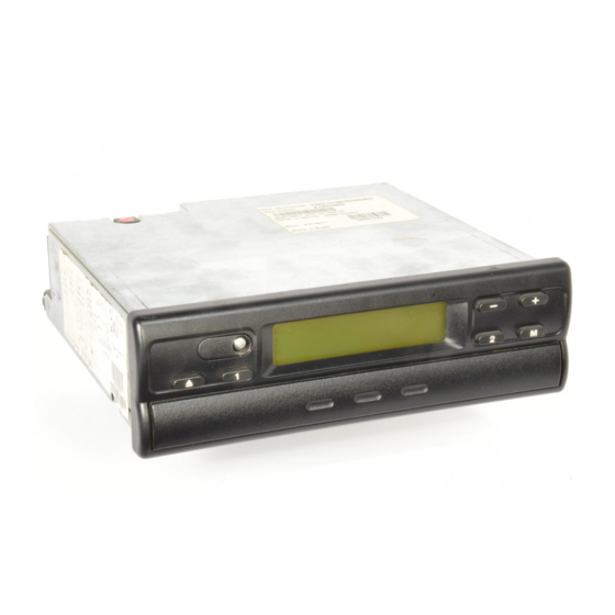
Operating controls Tachograph 1324... - Page 8 Operating controls (see figure page 3) 1 Left-hand keypad 4 Checkpoint marking for checking the temporally correct posi- Key for unlocking the drawer. tion of the chart carrier. Key for adjusting the time group for driver 1. 5 "Pear-shaped" chart carrier 2 Right-hand keypad 6 Separating plate Key for adjusting the time group...
-
Page 9: Enable The Device
Enable the device Opening the drawer 2. Pull out the hinged drawer to the limit The drawer may only be opened, stop and tip it down. if ... Remove driver 1 chart if necessary. the vehicle is at a standstill and the ignition is switched on. -
Page 10: Inserting The Driver 2 Chart
Enable the device Inserting the driver 2 chart 5. Tilt separating plate downwards. Before starting to drive, the centre field of the chart has to be duly recorded, see page 18. 4. The driver 2 inserts the recorded chart with the front side facing up in the "pear- shaped"... - Page 11 (d). Notes on the basic display The time of the tachograph 1324 is adju- sted to the legal time of the country where the vehicle has been registered. If this is not the case, please start the...
-
Page 12: Setting The Time Groups
= break times and resting periods Driver 1 Driver 2 As soon as the vehicle starts to drive, the tachograph 1324 will automatically record " " for driver 1 " " for driver 2 and the corresponding symbols will appear in the display. -
Page 13: Removing The Charts
" " for driver 1 and 2. The in the display. A process indicator sig- tachograph 1324 thus goes easy on the vehi- nals that the records on the charts are cle batteries. being completed by the Tacho- graph 1324. -
Page 14: Driver Change
Driver change Case 1: The crew changes among them- selves, driver 2 becomes driver 1 : 1. Exchange the charts. Driver 1 (now driver 2) places his chart below the separating plate and driver 2 (now driver 1) on the separat- ing plate. -
Page 15: Adjusting The Time
If you adjust the time while a chart is inserted, the er- ror symbol will be shown in the display and the time will be flashing. The tachograph 1324 will remind you to update the chart carrier settings; see page 15... -
Page 16: Messages
Messages The tachograph 1324 monitors the function- and notes may be shown in the display imme- ing of the system and automatically signals diately after having closed the drawer or any failure occurring in one of the compo- when the failure occurs. -
Page 17: Displaying The Error Memory
Messages Displaying the error memory To find out the reason for the error message please refer to the ERROR MEMORY menu. The display ERROR MEMORY function may only be selected if the vehicle is at a standstill! 1. Select the ERROR MEMORY menu by shortly depressing the key twice. -
Page 18: Error Code Overview
= Error at the drawer Start the ejection procedure and close the drawer again afterwards. = Error in recording system (The tachograph 1324 will record these errors on the chart, see page 20.) = Error during chart carrier settings update Update the chart carrier settings once again, see page 15. -
Page 19: Troubleshooting
(Error code cannot be found in the error memory.) Insert driver 1 chart. = Power loss (Error code cannot be found in the error memory. The tachograph 1324 will record a power loss on the chart, see page 20.) Error during sensor 2170 communication... -
Page 20: Description Of The Chart
The appropriate chart for the device When using (ordering) charts, always ensure that the full-scale value (1) and the approval mark (2) of the tachograph 1324 correspond to the details (3) or (4) on the chart respec- tively. Outside the EU, the respective national ap- proval marks and provisions are valid. -
Page 21: Recordings On The Front Part Of The Chart
Description of the chart Recordings on the front part of the chart 7 Distance travelled An up- or downward movement corresponds to 5 km. = 5km Note The distance recording will be interrupted if ... the time group switches have been set to break time "... -
Page 22: Entries In The Centre Field
Description of the chart Entries in the centre field a) ... before trip name and first name of the driver place of departure date of insertion (upper line) vehicle registration number beginning odometer reading b) ... after trip place of arrival date of chart retrieval (bottom line) ending odometer reading distance travelled (may be entered) -
Page 23: The Rear Side Of The Chart
1324 or else in case of a fail- ure of the time group recording mecha- nism. 2 Centre field In the centre field, up to three vehicle changes may be entered manually. -
Page 24: Recording Of Failures
Recording of failures Power loss In case there is power available again, the tachograph 1324 will draw a line (1) on the chart shortly after the vehicle has started to move. Sensor 2170 disconnection Failure of the transmission link between sensor 2170... -
Page 25: Appendix
Please ensure that the installation plate is At least once every two years, the proper op- replaced at each inspection and contains the eration of the tachograph 1324 has to be test- information required. Maintenance and cleaning The tachograph 1324 is equipped with modern, maintenance-free technology.
Need help?
Do you have a question about the 1324 and is the answer not in the manual?
Questions and answers