
Subscribe to Our Youtube Channel
Related Manuals for CAME EMEGA


Summary of Contents for CAME EMEGA
- Page 1 Automazione per porte basculanti FA01195M04 IT Italiano EM4024CB EN English FR Français RU Русский MANUALE DI INSTALLAZIONE...
-
Page 2: Leggere Attentamente
Ogni altro uso è da considerarsi pericoloso. usura o danni alle strutture mobili, ai componenti dell’automazione, a CAME S.p.A. non è responsabile per eventuali danni causati da usi tutti i punti e dispositivi di fi ssaggio, ai cavi e alle connessioni accessibili. - Page 3 ☞ Questo simbolo indica cosa comunicare all’utente. RIFERIMENTI NORMATIVI Came S.p.A.. è una azienda certificata per i sistemi di gestione aziendale: qualità ISO 9001 e ambientale ISO 14001. Il prodotto in oggetto è conforme alle normative vigenti citate nella dichiarazione di conformità.
-
Page 4: Descrizione Delle Parti
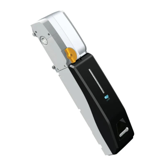
Descrizione delle parti Motoriduttore Coperchio Carter laterali Manopola di sblocco Scheda elettronica Scheda elettronica a LED per luce di cortesia Scheda di programmazione Vite UNI 5933 M4 x12 Viti UNI5737 M8X110 10. Dadi UNI5588 M8 11. Viti UNI6954 3,9X13 Dati tecnici Tipo EM4024CB Grado di protezione IP... -
Page 5: Impianto Tipo
Impianto tipo Automazione Fotocellule Tubo quadro di trasmissione (001E782A) Bordo sensibile Selettore a chiave Base di fissaggio (001E001) Coppia di bracci telescopici dritti con tubo rettangolare (001E785A) Trasmettitore Dispositivo di sblocco a cordino Lampeggiatore con antenna Accessori per il montaggio del rinvio laterale (001E781A) Esempi di applicazione Porta basculante a parziale rientranza a contrappesi o a molle. -
Page 6: Verifiche Preliminari
INDICAZIONI GENERALI PER L'INSTALLAZIONE ⚠ L’installazione deve essere effettuata da personale qualificato ed esperto e nel pieno rispetto delle normative vigenti. Verifiche preliminari ⚠ Prima di procedere all’installazione è necessario: • Prevedere adeguato dispositivo di disconnesione onnipolare, con distanza maggiore di 3 mm tra i contatti, a sezionamento dell’alimentazione;... -
Page 7: Installazione
INSTALLAZIONE ⚠ Le seguenti illustrazioni sono solo esempi e rappresentano il montaggio più diffuso, in quanto lo spazio per il fissaggio dell’automazione e degli accessori varia a seconda della zona di installazione. Spetta quindi all’installatore scegliere la soluzione più adatta. Nota: per applicazioni speciali, vedere il capitolo ESEMPI DI APPLICAZIONE PER PORTONI CON CARATTERISTICHE SPECIALI. - Page 8 Aprire completamente il portone e rilevare la misura B. Accorciare i bracci e i tubi telescopici. Nota: per portoni di altezza superiore a 2400 mm, utilizzare il tubo 001E787A per bracci telescopici. Rinvio laterale Togliere i carter laterali dal motoriduttore. Fissare il motoriduttore alla base con viti e dadi in dotazione.
- Page 9 Tagliare il tubo quadro di trasmissione. Inserire gli alberi quadri nell'albero motore lasciandoli sporgere di 35 mm e bloccarli con i grani di fissaggio e sbloccare il motoriduttore. Infilare i morsetti di giunzione al tubo di trasmissione.
- Page 10 Infilare il tubo di trasmissione nell'albero quadro e assemblarlo con la boccola e il braccio. Posizionare i morsetti di giunzione a circa 5 mm dalle estremità del tubo e fissarli con le piastrine e i grani di fissaggio. Ingrassare il braccio e infilarlo nel tubo telescopico.
-
Page 11: Sblocco Manuale Del Motoriduttore
Fissare il tubo telescopico al perno, sugli attacchi predisposti sul portone oppure utilizzando le staffe angolari in dotazione fissandole il più vicino possibile al braccio del portone. min. 15 mm 15 mm min. Sblocco manuale del motoriduttore ⚠ Far attenzione quando si aziona il dispositivo di rilascio manuale poiché una porta aperta può cadere improvvisamente a causa delle molle indebolite o rotte, oppure se è... - Page 12 Determinazione dei punti di finecorsa In apertura: con il motoriduttore sbloccato, portare il portone a circa 30 mm dall'apertura totale ❶. Ruotare la camma in senso antiorario fino a inserire il micro-interrutore ❷ e fissarla con le viti ❸. ❶ ❷...
- Page 13 COLLEGAMENTI ELETTRICI E PROGRAMMAZIONE La scheda elettronica va alimentata a 24 V AC. I dispoditivi di comando e gli accessori sono a 24 V AC. ⚠ Attenzione gli accessori non devono superare complessivamente i 40W. Le funzioni sui contatti di ingresso e uscita, le regolazioni dei tempi e la gestione degli utenti, vengono impostate e visualizzate sul display della scheda di programmazione gestito da un software.
- Page 14 Prima di procedere con i collegamenti elettrici, forare con cautela sul foro presfondato ❶. Togliere il coperchio ❷ e con attenzione, scollegare il cavo piatto dalla scheda elettronica ❸. Fissare la parte inferiore del contenitore del quadro comando alla base con la vite in dotazione ❹. Montare il pressacavo e il tubo corrugato (entrambi non in dotazione) mantenendo il grado di protezione IP40 ❺.
-
Page 15: Dispositivi Di Comando
Collegamento del secondo motoriduttore Automazione EM4024CB Motoriduttore EM4024. Microinterruttore di finecorsa in apertura FCA 2 M2 N2 M1 N1 + Enc2 - + Enc1 - 24 0 Dispositivi di comando Nota: applicare una ferrite (tipo RICHCO art. RT-250-150- 120-K5B, non fornita) sui cavi dei pulsanti di comando e delle... - Page 16 Scheda RSE per la gestione delle funzioni in modalità CRP (controllo domotico). 10 11 E RX TX 1 2 3 5 7 2 CX CY B GND CRP - Came Remote Protocoll. Collegamento all'impianto domotico Lampadina spia porta aperta (Portata contatto: 24 V - 3 W max.).
-
Page 17: Dispositivi Di Sicurezza
Dispositivi di sicurezza Fotocellule 10 11 E RX TX 1 2 3 5 7 2 CX CY B GND Configurare il contatto CX o CY (N.C.), ingresso per dispositivi di sicurezza tipo fotocellule, conformi alle normative EN 12978. Vedi funzioni ingresso CX (Funzione F2) o CY (Funzione F3) in: 2 TX - C1 riapertura durante la chiusura, in fase di... - Page 18 Collegamento di sicurezza delle fotocellule A ogni comando di apertura o di chiusura, la scheda verifica che le fotocellule funzionino. Un’eventuale anomalia inibisce qualsiasi comando. Selezionare dalla funzione F 5 su quali ingressi attivare il collegamento. DIR / DELTA S DELTA FUSIBILE 200mA 10 2 TX C...
-
Page 19: Navigazione Menu
Memorizzazione dati Per inserire, modificare e rimuovere gli utenti o comandare l’automazione mediante comando radio, inserire la scheda AF. Inserire la memory roll per salvare e caricare le impostazioni e gli utenti registrati in Memory roll un’altra scheda. Scheda AF Descrizione dei comandi di programmazione Display Il tasto ENTER serve per:... - Page 20 Mappatura del menu Funzione stop totale (1-2) Funzione associata all’ingresso 2-CX Funzione associata all’ingresso 2-CY Funzione test sicurezza Funzione azione mantenuta Modalità comando su 2-7 Modalità comando su 2-3 / 2-3P Funzione rilevazione ostacolo a motore fermo F 11 Esclusione Encoder F 13 Spinta in chiusura F 18...
-
Page 21: Menu Funzioni
Menu funzioni Stop totale [1-2] 0 = Disattivata (default) / 1 = Attivata Ingresso N.C. – Stop della porta con esclusione dell’eventuale chiusura automatica; per riprendere il movimento, usare il dispositivo di comando. Il dispositivo di sicurezza va inserito su [1-2]. Ingresso [2-CX] 0 = Disattivata (default) / 1 = C1 / 4 = C4 / 7 = C7 Ingresso N.C. - Page 22 Velocità motore apre 50 = Velocità minima /… / 70 = Velocità (default) /… / 100 = Velocità massima Per l’impostazione della velocità del motoriduttore durante le manovre di apertura. Velocità motore chiude 20 = Velocità minima /… / 50 = Velocità (default) /… / 100 = Velocità massima Per l’impostazione della velocità...
- Page 23 Menu utenti Inserimento utente 1 = Comando passo-passo (apre-chiude) / 2 = Comando sequenziale (apre-stop- chiude-stop) / 3 = Comando solo apre / 4 = Comando pedonale/parziale Inserimento utente (max. 25 utenti) associato ad un comando mediante trasmettitore o altro dispositivo (vedi pararagrafo inserimento utente con comando associato).
- Page 24 Cancellazione di un singolo utente Selezionare U 2. Premere ENTER per confermare ❶. Scegliere il numero dell'utente da cancellare mediante tasti contrassegnati con le frecce. Premere ENTER per confermare ❷. Verrà visualizzata la scritta Clr a confermare la cancellazione ❸. ❶...
- Page 25 Taratura corsa N.B.: prima di eff ettuare la taratura della corsa, controllare che l’area di manovra sia libera da qualsiasi ostacolo. Importante! Durante la taratura, tutti dispositivi di sicurezza saranno disabilitati escluso quello per lo STOP TOTALE. Selezionare A 3. Premere ENTER per confermare ❶. Selezionare 1 e premere ENTER per confermare ❷.
- Page 26 ESEMPI DI APPLICAZIONE PER PORTE CON CARATTERISTICHE SPECIALI Porta basculante snodata a contrappesi o a molle con guida cuscinetto di minimo 25 mm con motoriduttore applicato centralmente Applicare la base-guida (001E001) e la staffa di ancoraggio come da figura 1 rispettando le quote vedi tabella. Assemblare i bracci snodati (001E783) come da figura 2 e procedere con l'installazione del motoriduttore, rinvii e il tubo di trasmissione seguendo la procedura riportata nei paragrafi precedenti.
- Page 27 Porta basculante a contrappesi o a molle con guida cuscinetto di minimo 25 mm con motoriduttore applicato centralmente Applicare la base-guida (001E001) e la staffa di ancoraggio come da figura 1 rispettando le quote vedi tabella. Assemblare i bracci snodati (001E783) come da figura 2 e procedere con l'installazione del motoriduttore, rinvii e il tubo di trasmissione seguendo la procedura riportata nei paragrafi precedenti.
- Page 28 Porta basculante a contrappesi o a molle senza guida cuscinetto avente spazio utile tra telaio porta e carter del contrappeso non inferiore a 15 mm con motoriduttore applicato centralmente Applicare la base-guida (001E001) e la staffa di ancoraggio come da figura rispettando le quote vedi tabella. Applicare i bracci telescopici curvi (001E786A) e procedere con l'installazione del motoriduttore, rinvii e il tubo di trasmissione seguendo la procedura riportata nei paragrafi precedenti.
- Page 29 Porta basculante a contrappesi non debordante con motoriduttore applicato centralmente Applicare la base-guida (001E001) e la staffa di ancoraggio come da figura rispettando le quote vedi tabella. Assemblare i bracci telescopici dritti (001E785A) e procedere con H /2 l'installazione del motoriduttore, rinvii E 7 8 5 A e il tubo di trasmissione seguendo la procedura riportata nei paragrafi...
-
Page 30: Manutenzione Periodica
MANUTENZIONE Manutenzione periodica ☞ Prima di qualsiasi operazione di manutenzione, togliere la tensione, per evitare possibili situazioni di pericolo causate da accidentali movimentazioni del dispositivo. Registro manutenzione periodica a cura dell’utente (semestrale) Data Annotazioni Firma Manutenzione straordinaria ⚠ La seguente tabella serve per registrare gli interventi di manutenzione straordinaria, di riparazione e di miglioramento eseguiti da ditte esterne specializzate. - Page 31 DISMISSIONE E SMALTIMENTO ☞ CAME S.p.A. implementa all’interno dei propri stabilimenti un Sistema di Gestione Ambientale certificato e conforme alla norma UNI EN ISO 14001 a garanzia del rispetto e della tutela dell’ambiente. Vi chiediamo di continuare l’opera di tutela dell’ambiente, che CAME considera uno dei fondamenti di sviluppo delle proprie strategie operative e di mercato, semplicemente osservando brevi indicazioni in materia di smaltimento: SMALTIMENTO DELL’IMBALLO...
- Page 32 CAME S.p.A. Via Martiri Della Libertà, 15 31030 Dosson di Casier - Treviso - Italy tel. (+39) 0422 4940 - fax. (+39) 0422 4941...
- Page 33 Operator for overhead doors FA01195-EN EM4024CB EN English INSTALLATION MANUAL...
-
Page 34: Read Carefully
• This product should only be used for the purpose for which it was the same where friction may occur (i.e. slide rails) • Perform functional explicitly designed. Any other use is considered dangerous. CAME tests on photocells and sensitive edges every six months. To check that S.p.A.. -
Page 35: Packing List
1 x installation manual Intended use The operator has been designed and built by CAME Cancelli S.p.A.. in compliance with current safety standards to motorise medium and large overhead doors for residential or condominium use with intensive service. Any installation and operation that differs from what is set out in this manual is prohibited. -
Page 36: Description Of The Components
Description of the components Gearmotor Cover Side casing Release handle Control board LED control board for courtesy light Programming card UNI 5933 M4 x12 screw UNI 5737 M8X110 screws 10. UNI 5588 M8 nuts 11. UNI 6954 3,9X13 screws Technical data Type EM4024CB IP rating... -
Page 37: Example Of A System
Example of a system Operator Photocells Transmission board tube (001E782A) Sensitive edge Key selector Fixing base (001E001) Pair of straight telescopic arms with rectangular tube (001E785A) Transmitter Pull-cord release device Flashing light with antenna Accessories for assembling the lateral transmission (001E781A) Examples of use Canopy and spring-balanced overhead doors, with partially retracting movement. -
Page 38: General Installation Instructions
GENERAL INSTALLATION INSTRUCTIONS ⚠ Installation must be carried out by qualified and experienced personnel in compliance with applicable regulations. Preliminary checks ⚠ Before starting installation: • Provide a suitable single-pole disconnection device, with a maximum of 3 mm between the contacts, to disconnect the power supply;... -
Page 39: Installation
INSTALLATION ⚠ The following illustrations are only examples and show the most common type of assembly, given that the space for securing the operator and accessories varies depending on the place of installation. The installation technician is responsible for choosing the most suitable solution. - Page 40 Open the door fully and take measurement B . Shorten the arms and telescopic tubes. N.B. For doors of higher than 2400 mm, use the 001E787A tube for telescopic arms. Lateral transmission Remove the side casing from the gearmotor. Secure the gearmotor to the base using the screws and nuts supplied. UNI 5588 M8 UNI 5737 M8 x 110...
- Page 41 Cut the transmission board tube. Insert the square shafts in the motor shaft, allowing them to protrude by 35 mm and secure them using the fixing grub screws and release the gearmotor. Insert the connecting terminals in the transmission tube.
- Page 42 Insert the transmission tube into the square shaft and assemble it with the bushing and the arm. Position the connecting clamps about 5 mm from the ends of the tube and secure them using the plates and fixing grub screws. Grease the arm and slide it into the telescopic tube.
- Page 43 Secure the telescopic tube to the pin, on the connectors on the door or using the angular brackets supplied, securing them as close as possible to the arm of the door. min. 15 mm 15 mm min. Manual release of the gearmotor ⚠ Be careful when operating the manual release device as an open leaf may abruptly fall due to weakened or broken springs, or if unbalanced.
- Page 44 Determining the end run points During opening: with the gearmotor released, move the door to about 30 mm from total opening ❶. Turn the cam anti-clockwise until the microswitch is engaged ❷ and secure it with the screws ❸. ❶ ❷...
-
Page 45: Fuse Table
ELECTRICAL CONNECTIONS AND PROGRAMMING The control board is powered at 24 VAC. The control devices and accessories are powered at 24 VAC. ⚠ Caution - the total power of the accessories should not exceed 40 W. The functions on the input and output contacts and the adjustments of the times and management of the users are set and viewed on the display on the programming card managed by a software program. -
Page 46: Power Supply
Before proceeding with the electrical connections, drill the pre-made holes carefully ❶. Remove the cover ❷ and carefully disconnect the flat cable from the control board ❸. Secure the bottom of the control panel container to the base using the screw supplied ❹. Install the cable gland and the corrugated tube (neither supplied) maintaining IP40 protection rating ❺. -
Page 47: Control Devices
Connecting the second gearmotor EM4024CB operator EM4024 gearmotor. Opening micro limit switch FCA 2 M2 N2 M1 N1 + Enc2 - + Enc1 - 24 0 Note: fit a Control devices RICHCO type ferrite, art. RT-250-150- 120-K5B, (not supplied) onto the cables of the control button and photocells. - Page 48 RSE card for function management in CRP mode (home automation control). 10 11 E RX TX 1 2 3 5 7 2 CX CY B GND CRP - Came Remote Protocol. Connecting to the home automation system Door open indicator light (Contact capacity: 24 V - 3 W max.).
-
Page 49: Safety Devices
Safety devices Photocells 10 11 E RX TX 1 2 3 5 7 2 CX CY B GND Configure the CX or CY (NC) contact, input for safety devices such as photocells, compliant with the EN 12978 standard. See CX (F2 function) or CY (F3 function) input functions in: 2 TX - C1 reopening during closing. - Page 50 Photocell safety connection With each opening or closing command, the panel checks that the photocells work. Any anomaly inhibits any command. Use the F 5 function to select on which inputs to activate the link. DIR / DELTA S DELTA FUSIBILE 200mA 10 2 TX C 10 11 E RX TX 1 2 3 5 7 2 CX CY...
-
Page 51: Menu Navigation
Memorising data To enter, modify, and remove users or control the operator via radio, insert the AF card. Insert the memory roll to save and load the settings and registered users on another card. Memory roll AF card Description of programming commands Display The ENTER key is used to: - access the menus;... - Page 52 Menu mapping Total stop function (1-2) Function associated with the 2-CX input Function associated with the 2-CY input Safety test function Hold-to-run function Command mode on 2-7 Command mode on 2-3 / 2-3P Obstacle detection with motor at standstill function F 11 Encoder disabled F 13...
-
Page 53: Function Menu
Function menu Total stop [1-2] 0 = Disabled (default) / 1 = Enabled NC input - The door is stopped and any automatic closing is disabled. To resume movement, use the control device. The safety device must be inserted on [1-2]. Input [2-CX] 0 = Disabled (default) / 1 = C1 / 4 = C4 / 7 = C7 NC input - Possibility of associating: C1 = reopening during closing for photocells, C4 = obstacle wait, C7 = reopening... - Page 54 Open motor speed 50 = Minimum speed /… / 70 = Speed (default) /… / 100 = Maximum speed To set the gearmotor speed during the opening manoeuvres. Close motor speed 20 = Minimum speed /… / 50 = Speed (default) /… / 100 = Maximum speed To set the gearmotor speed during the closing manoeuvres.
- Page 55 User menu Adding a user 1 = Step-by-step command (open-close) / 2 = Sequential command (open-stop-close- stop) / 3 = Open only command / 4 = Pedestrian/partial command Adding a user (max. 25 users) associated with a command via the transmitter or other device (see adding a user with associated command paragraph).
-
Page 56: Deleting A Single User
Deleting a single user Select U 2. Press ENTER to confirm ❶. Choose the number of the user to delete using the keys marked with arrows. Press ENTER to confirm ❷. Clr appears to confirm the deletion ❸ . ❶ ❷... -
Page 57: Run Calibration
Run calibration N.B. before calibrating the run, check that the manoeuvre area is free from any obstacle. Important! During calibration, all safety devices will be disabled except for the TOTAL STOP device. Select A 3. Press ENTER to confirm ❶. Select 1 and press ENTER to confirm ❷. - Page 58 EXAMPLES OF APPLICATION ON DOORS WITH SPECIAL CHARACTERISTICS. Hinged canopy or spring-balanced overhead door with minimum 25 mm bearing guide and gearmotor applied centrally Apply the guide-base (001E001) and the anchoring bracket as shown in figure 1 according to the dimensions, see table. Assemble the articulated arms (001E783) as shown in figure 2 to proceed with the installation of the gearmotor, returns and the transmission tube using the procedure described in the previous paragraphs.
- Page 59 Canopy or spring-balanced overhead door with minimum 25 mm bearing guide and gearmotor applied centrally Apply the guide-base (001E001) and the anchoring bracket as shown in figure 1 according to the dimensions, see table. Assemble the articulated arms (001E783) as shown in figure 2 to proceed with the installation of the gearmotor, returns and the transmission tube using the procedure described in the previous paragraphs.
- Page 60 Canopy or spring-balanced overhead door without bearing guide and clearance between the door frame and counterweight casing of not less than 15 mm with gearmotor applied centrally. Apply the guide-base (001E001) and the anchoring bracket as shown in the figure according to the dimensions, see table. Apply the curved telescopic arms (001E786A) and proceed with the installation of the gearmotor, returns and the transmission tube following the procedure set out in the previous paragraphs.
- Page 61 Non-protruding counter-weighted overhead garage-door with gearmotor fitted centrally. Apply the guide-base (001E001) and the anchoring bracket as shown in the figure according to the dimensions, see table. Assemble the straight telescopic arms (001E785A) and proceed with the H /2 installation of the gearmotor, returns E 7 8 5 A and the transmission tube following the procedure set out in the previous...
-
Page 62: Periodic Maintenance
MAINTENANCE Periodic maintenance ☞ Before any maintenance, disconnect power to prevent any possible dangerous situations that can be caused by accidental movement of the device. Periodic maintenance log to be completed by the user (every six months) Date Notes Signature Extraordinary maintenance ⚠... - Page 63 CAME S.p.A. implements an EN ISO 14001 certified and compliant Environmental Management System at its plants, to ensure environmental protection. Please continue our efforts to protect the environment, something that CAME considers to be one of the foundations in developing its business and market strategies, simply by observing brief recommendations as regards disposal: DISPOSAL OF PACKAGING Packaging components (cardboard, plastic etc.) can be disposed of together with normal household waste without any difficulty, by simply...
- Page 64 CAME S.p.A. Via Martiri Della Libertà, 15 31030 Dosson di Casier - Treviso - Italy tel. (+39) 0422 4940 - fax. (+39) 0422 4941...
-
Page 65: Manuel D' Installation
Automatisme pour portes basculantes FA01195-FR EM4024CB FR Français MANUEL D’ INSTALLATION... - Page 66 Toute autre utilisation est à considérer comme de l'automatisme, tous les points et dispositifs de fi xation, les câbles et dangereuse. La société CAME S.p.A.. décline toute responsabilité en les connexions accessibles. Les points d'articulation (charnières) et de cas d'éventuels dommages provoqués par des utilisations impropres,...
-
Page 67: Références Normatives
☞ Ce symbole indique ce qui doit être communiqué à l'utilisateur. RÉFÉRENCES NORMATIVES Came S.p.A.. est une société certifiée pour les systèmes de gestion de la qualité ISO 9001 et de gestion environnementale ISO 14001. Le produit en question est conforme aux normes en vigueur citées dans la déclaration de conformité. -
Page 68: Description Des Parties
Description des parties Motoréducteur Couvercle Carters latéraux Poignée de déblocage Carte électronique Carte électronique à LEDs pour lampe d'accueil Carte de programmation Vis UNI 5933 M4 x12 Vis UNI5737 M8X110 10. Écrous UNI5588 M8 11. Vis UNI6954 3.9X13 Données techniques Type EM4024CB Degré... -
Page 69: Installation Type
Installation type Automatisme Accessoires pour le montage de la Tube de transmission carré (001E782A) butée latérale (001E781A) Photocellules Base de fixation (001E001) Paire de bras télescopiques droits avec tube rectangulaire Bord sensible (001E785A) Sélecteur à clé Dispositif de déblocage par câble Émetteur Feu clignotant avec antenne Exemples d'application... -
Page 70: Contrôles Préliminaires
INSTRUCTIONS GÉNÉRALES POUR L'INSTALLATION ⚠ L’installation doit être effectuée par du personnel qualifié et dans le plein respect des normes en vigueur. Contrôles préliminaires ⚠ Avant de procéder à l'installation, il faut : • Prévoir un dispositif de déconnexion omnipolaire spécifique, avec un espace de plus de 3 mm entre les contacts, pour le sectionnement de l'alimentation. -
Page 71: Caractéristiques Spéciales
INSTALLATION ⚠ Les illustrations suivantes ne sont que des exemples et représentent le montage le plus fréquent, étant donné que l'espace pour la fixation de l'automatisme et des accessoires varie en fonction de la zone d'installation. C'est donc l'installateur qui doit choisir la solution la plus indiquée. - Page 72 Ouvrir complètement la porte et noter la mesure B. Raccourcir les bras et les tubes télescopiques. Remarque : pour les portes de plus de 2 400 mm de haut, utiliser le tube 001E787A pour bras télescopiques. Butée latérale Enlever les carters latéraux du motoréducteur. Fixer le motoréducteur à...
- Page 73 Couper le tube de transmission carré. Introduire les arbres carrés dans l'arbre moteur en les laissant dépasser de 35 mm et les bloquer à l'aide de goujons de fixation. Débloquer ensuite le motoréducteur. Enfiler les éléments de jonction sur le tube de transmission.
- Page 74 Introduire le tube de transmission dans l'arbre carré et l'assembler à la douille et au bras. Positionner les éléments de jonction à environ 5 mm des extrémités du tube et les fixer à l'aide des plaques et des goujons de fixation.
- Page 75 Fixer le tube télescopique au goujon, sur les éléments de fixation prévus sur la porte ou bien à l'aide des étriers angulaires fournis à fixer le plus près possible du bras de la porte. min. 15 mm 15 mm min. Déblocage manuel du motoréducteur ⚠ Faire attention lors de l'actionnement du dispositif de relâchement manuel qui pourrait provoquer la chute brusque d'une porte ouverte qui serait déséquilibrée ou dont les ressorts seraient usés ou cassés.
- Page 76 En phase d'ouverture : avec motoréducteur débloqué, amener la porte à environ 30 mm de l'ouverture totale ❶. Tourner la came dans le sens contraire à celui des aiguilles d'une montre jusqu'à l'actionnement du minirupteur ❷ et la fixer à l'aide de vis ❸.
- Page 77 BRANCHEMENTS ÉLECTRIQUES ET PROGRAMMATION La carte électronique doit être alimentée à 24 V AC. Les dispositifs de commande et les accessoires sont alimentés à 24 V AC. ⚠ Attention ! Les accessoires ne doivent pas dépasser tous ensemble 40 W. Les fonctions sur les contacts d'entrée et de sortie, les réglages des temps et la gestion des utilisateurs sont configurés et visualisés sur l'afficheur de la carte de programmation géré...
- Page 78 Avant d'effectuer les branchements électriques, percer avec prudence le trou préforé ❶. Enlever le couvercle ❷ et déconnecter avec soin le câble plat de la carte électronique ❸. Fixer la partie inférieure du boîtier de l'armoire de commande à la base à l'aide de la vis fournie ❹. Installer le serre-câble et le tuyau annelé...
-
Page 79: Dispositifs De Commande
Connexion du deuxième motoréducteur Automatisme EM4024CB Motoréducteur EM4024. Minirupteur de fin de course en phase d'ouverture FCA 2 M2 N2 M1 N1 + Enc2 - + Enc1 - 24 0 Remarque : appliquer une Dispositifs de commande ferrite (type RICHCO art. RT-250-150- 120-K5B, non fournie) sur... - Page 80 Carte RSE pour la gestion des fonctions en modalité CRP (contrôle domotique). 10 11 E RX TX 1 2 3 5 7 2 CX CY B GND CRP - Came Remote Protocoll. Connexion à Lampe témoin porte ouverte l'installation domotique. (Portée contact : 24 V - 3 W max.).
-
Page 81: Dispositifs De Sécurité
Dispositifs de sécurité Photocellules 10 11 E RX TX 1 2 3 5 7 2 CX CY B GND Configurer le contact CX ou CY (N.F.), entrée pour dispositifs de sécurité type photocellules, conformes aux normes EN 12978. Voir fonctions entrée CX (Fonction F2) ou CY (Fonction F3) en : 2 TX - C1 réouverture durant la fermeture, durant... - Page 82 Connexion de sécurité des photocellules La carte contrôle le bon fonctionnement des photocellules à chaque commande d'ouverture ou de fermeture. Les anomalies, quelles qu'elles soient, désactivent les commandes. Sélectionner par le biais de la fonction F 5 les entrées sur lesquelles activer la connexion. DIR / DELTA S DELTA FUSIBILE 200mA...
-
Page 83: Mémorisation Des Données
Mémorisation des données Pour insérer, modifier et éliminer les utilisateurs ou commander l'automatisme par commande radio, insérer la carte AF. Insérer la mémoire pour sauvegarder et télécharger les configurations et les Memory roll utilisateurs enregistrés dans une autre carte. Carte AF Description des commandes de programmation Afficheur La touche ENTER permet de/d' :... - Page 84 Mappage du menu Fonction arrêt total (1-2) Fonction associée à l'entrée 2-CX Fonction associée à l'entrée 2-CY Fonction test sécurité Fonction action maintenue Modalité commande sur 2-7 Modalité commande sur 2-3 / 2-3P Fonction détection obstacle avec moteur éteint F 11 Désactivation Encodeur F 13 Poussée en phase de fermeture...
-
Page 85: Menu Fonctions
Menu fonctions Arrêt total [1-2] 0 = Désactivée (par défaut) / 1 = Activée Entrée N.F. – Arrêt de la porte avec désactivation de l'éventuelle fermeture automatique ; pour reprendre le mouvement, utiliser le dispositif de commande. Le dispositif de sécurité doit être positionné sur [1-2]. Entrée [2-CX] 0 = Désactivée (par défaut) / 1 = C1 / 4 = C4 / 7 = C7 Entrée N.F. - Page 86 Vitesse moteur ouverture 50 = Vitesse minimale /… / 70 = Vitesse (par défaut) /… / 100 = Vitesse maximale Pour la confi guration de la vitesse du motoréducteur durant les manœuvres d'ouverture. Vitesse moteur fermeture 20 = Vitesse minimale /… / 50 = Vitesse (par défaut) /… / 100 = Vitesse maximale Pour la confi...
-
Page 87: Menu Infos
Menu utilisateurs Insertion utilisateur 1 = Commande pas-à-pas (ouverture-fermeture) / 2 = Commande séquentielle (ouverture-arrêt-fermeture-arrêt) / 3 = Commande ouverture seulement / 4 = Commande piétonne/partielle Insertion utilisateur (max. 25 utilisateurs) associé à une commande par émetteur ou autre dispositif (voir paragraphe insertion utilisateur avec commande associée). - Page 88 Élimination d'un seul utilisateur Sélectionner U 2. Appuyer sur ENTER pour confirmer ❶. Choisir le numéro de l'utilisateur à éliminer à l'aide des touches signalées par les flèches. Appuyer sur ENTER pour confirmer ❷. L'écran affichera Clr pour confirmer l'élimination ❸. ❶...
- Page 89 Réglage course N.B. : avant de régler la course, s'assurer que la zone d'actionnement ne présente aucun obstacle. Important ! Durant le réglage, tous les dispositifs de sécurité seront désactivés, sauf le dispositif d'ARRÊT TOTAL. Sélectionner A 3. Appuyer sur ENTER pour confirmer ❶. Sélectionner 1 et appuyer sur ENTER pour confirmer ❷.
- Page 90 EXEMPLES D'APPLICATION POUR PORTES AUX CARACTÉRISTIQUES SPÉCIALES Porte basculante articulée à contrepoids ou à ressorts avec glissière à roulement d'au moins 25 mm et motoréducteur positionné au centre Appliquer la base de guidage (001E001) et la bride de fixation comme indiqué sur la figure 1 en respectant les dimensions fournies dans le tableau.
- Page 91 Porte basculante à contrepoids ou à ressorts avec glissière à roulement d'au moins 25 mm et motoréducteur positionné au centre Appliquer la base de guidage (001E001) et la bride de fixation comme indiqué sur la figure 1 en respectant les dimensions fournies dans le tableau.
- Page 92 Porte basculante à contrepoids ou à ressorts sans glissière à roulement avec espace entre le cadre de la porte et le carter du contrepoids non inférieur à 15 mm avec motoréducteur positionné au centre Appliquer la base de guidage (001E001) et la bride de fixation comme indiqué sur la figure en respectant les dimensions fournies dans le tableau.
- Page 93 Porte basculante à contrepoids non débordante avec motoréducteur positionné au centre Appliquer la base de guidage (001E001) et la bride de fixation comme indiqué sur la figure en respectant les dimensions fournies dans le tableau. Appliquer les bras télescopiques droits H /2 (001E785A) et installer le motoréducteur, E 7 8 5 A...
-
Page 94: Entretien Périodique
ENTRETIEN Entretien périodique ☞ Avant toute autre opération d'entretien, il est conseillé de mettre hors tension pour éviter toute situation de danger provoquée par des déplacements accidentels du dispositif. Registre entretien périodique tenu par l'utilisateur (semestriel) Date Remarques Signature Entretien curatif ⚠... -
Page 95: Élimination De L'emballage
(ex. : photocellules, bouton d'arrêt). MISE AU REBUT ET ÉLIMINATION ☞ CAME S.p.A. adopte dans ses établissements un Système de Gestion Environnementale certifié et conforme à la norme UNI EN ISO 14001 qui garantit le respect et la sauvegarde de l'environnement. - Page 96 CAME S.p.A. Via Martiri Della Libertà, 15 31030 Dosson di Casier - Treviso - Italy tel. (+39) 0422 4940 - fax. (+39) 0422 4941...
-
Page 97: Руководство По Установке
Автоматика для подъемно-поворотных ворот FA01195-RU EM4024CB RU Pусский РУКОВОДСТВО ПО УСТАНОВКЕ... - Page 98 неполадок в работе или других следов износа или повреждений на назначению. Любое другое применение рассматривается как опасное. подвижных конструкциях, компонентах автоматической системы, CAME S.p.A.. снимает с себя всякую ответственность за возможный местах крепления, проводке и доступных подключениях. Следите ущерб, нанесенный в результате неправильного использования...
-
Page 99: Условные Обозначения
⚠ Этот символ обозначает раздел, связанный с вопросами безопасности. ☞ Этот символ обозначает раздел, предназначенный для ознакомления конечного пользователя. НОРМЫ И СТАНДАРТЫ CAME имеет сертификат систем управления качеством ISO 9001 и сертификат охраны окружающей среды ISO 14001. Настоящее изделие соответствует требованиям нормативов, указанных в декларации о соответствии. -
Page 100: Основные Компоненты
Основные компоненты Привод Крышка Боковые крышки Ручка разблокировки Плата блока управления Светодиодная плата лампы дополнительного освещения Плата программирования Винт UNI 5933 M4 x12 Винты UNI5737 M8X110 10. Гайки UNI 5588 M8 11. Винты UNI6954 3,9X13 Технические характеристики Модель EM4024CB Класс защиты (IP) Электропитание... -
Page 101: Варианты Установки
Вариант типовой установки Привод Фотоэлементы Труба передачи квадратного сечения (001E782A) Чувствительный профиль Монтажное основание (001E001) Ключ-выключатель Комплект прямых телескопических рычагов с трубой Брелок-передатчик прямоугольного сечения (001E785A) Сигнальная лампа с антенной Трос (для дистанционной разблокировки) Принадлежности для монтажа передающей системы (001E781A) Варианты... -
Page 102: Предварительные Проверки
ОБЩИЕ ИНСТРУКЦИИ ПО МОНТАЖУ ⚠ Монтаж должен производиться квалифицированным персоналом в полном соответствии с требованиями действующих норм безопасности. Предварительные проверки ⚠ Перед тем как приступить к монтажным работам, выполните следующее: • Убедитесь в том, что питание блока управления осуществляется от отдельной линии с соответствующим автоматическим... - Page 103 МОНТАЖ ⚠ Приведенные ниже рисунки иллюстрируют наиболее распространенный вариант установки и носят ориентировочный характер, так как пространство для крепления автоматики и дополнительных принадлежностей может меняться от случая к случаю. Таким образом, выбор наиболее подходящего решения должен осуществляться монтажником на месте. Примечание: о...
- Page 104 Полностью откройте ворота и измерьте расстояние В. Укоротите составляющие телескопических рычагов. Примечание: для ворот высотой более 2400 мм необходимо использовать удлиненную трубу 001E787A для телескопических рычагов. Опора передающей системы Снимите боковые крышки привода. Закрепите привод на монтажном основании с помощью прилагаемых болтов и шайб. UNI 5588 M8 UNI 5737 M8 x 110...
- Page 105 Подготовьте трубы передачи квадратного сечения, отрезав излишек. Вставьте валы квадратного сечения в приводной вал таким образом, чтобы они выходили на 35 мм наружу. Зафиксируйте их с помощью штифтов и разблокируйте привод. Установите соединительные зажимы на трубы передачи.
- Page 106 Соедините трубу передачи сначала с валом квадратного сечения, а затем через втулку с рычагом. Установите соединительные зажимы на расстоянии 5 мм от края и зафиксируйте их с помощью пластин и штифтов. Смажьте рычаг и вставьте его в трубу.
- Page 107 Прикрепите трубу телескопического рычага к стержню, посредством креплений, специально предусмотренных на полотне ворот, или прилагаемых крепежных уголков, установив их как можно ближе к рычагу ворот. мм (мин.) min. 15 mm 15 mm min. Ручная разблокировка привода ⚠ Будьте внимательны при использовании устройства ручной разблокировки, поскольку открытые ворота могут неожиданно...
- Page 108 Определение крайних положений При открывании: разблокируйте привод и откройте ворота, остановив их на расстоянии приблизительно 30 мм от точки максимального открывания ❶. Вращайте кулачок против часовой стрелки до тех пор, пока не сработает концевой микровыключатель ❷, и зафиксируйте его с помощью винтов ❸. ❶...
- Page 109 ЭЛЕКТРИЧЕСКИЕ ПОДКЛЮЧЕНИЯ И ПРОГРАММИРОВАНИЕ Плата управления питается напряжением ~24 В. Для электропитания устройств управления и аксессуаров используется напряжение ~24 В. ⚠ Внимание! Суммарная мощность дополнительных устройств не должна превышать 40 Вт. Установка функций входных/выходных контактов, режимов работы и регулировок осуществляется с помощью дисплея...
- Page 110 Перед выполнением электрических подключений осторожно рассверлите отверстие в предварительно размеченном месте ❶. Снимите крышку ❷ и аккуратно отсоедините шлейф платы управления ❸. Прикрепите нижнюю часть корпуса блока управления к монтажному основанию с помощью прилагаемого винта ❹. Установите гермоввод и гофрированную трубу (не входят в комплект) с классом защиты IP40 ❺. ❷...
- Page 111 Подключение второго привода Привод EM4024CB Привод EM4024 Концевой микровыключатель открывания FCA 2 M2 N2 M1 N1 + Enc2 - + Enc1 - 24 0 Примечание: установите Устройства управления феррит (типа RICHCO арт. RT-250-150- 120-K5B, не поставляется в комплекте) на провода кнопок управления...
- Page 112 функциями в режиме CRP (удаленное управление "умным домом"). 10 11 E RX TX 1 2 3 5 7 2 CX CY B GND CRP — Came Remote Protocoll (протокол удаленного доступа Лампа-индикатор "Ворота открыты" Came). Подключение (макс. нагрузка: 24 В, макс. 3 Вт).
-
Page 113: Устройства Безопасности
Устройства безопасности Фотоэлементы 10 11 E RX TX 1 2 3 5 7 2 CX CY B GND Выберите режим работы контакта CX (Н.З.) или CY (Н.З.), предназначенного для подключения устройств безопасности, например, фотоэлементов, соответствующих требованиям норматива EN 12978. Режим работы контакта CX (Функция F2) или... - Page 114 Самодиагностика фотоэлементов безопасности При каждой команде открывания или закрывания ворот плата проверяет эффективность работы фотоэлементов. При обнаружении неисправности в работе фотоэлементов любая команда управления воротами блокируется. Выберите функцию F 5 для тех контактов, к которым подключены DIR / DELTA S устройства, требующие...
-
Page 115: Навигация По Меню
Сохранение данных Для создания, изменения и удаления пользователей или управления автоматикой с помощью устройств радиоуправления необходимо вставить в разъем плату радиоприемника AF43S. Карта памяти Вставьте карту памяти для сохранения или загрузки зарегистрированных Плата пользователей и их настроек. радиоприемника Описание команд программирования Дисплей... -
Page 116: Структура Меню
Структура меню Функция "Стоп" (1-2) Функция, присвоенная входным контактам 2-CX Функция, присвоенная входным контактам 2-CY Функция самодиагностики устройств безопасности Функция управления в режиме "Присутствие оператора" Режим управления для контактов 2-7 Режим управления для контактов 2-3 / 2-3P Функция обнаружения препятствия при остановленном приводе F 11 Отключение... - Page 117 Меню «Функции» Функция "Стоп" [1-2] 0 = Отключена (по умолчанию) / 1 = Включена Н.З. контакты. – Данная функция позволяет остановить ворота с последующим исключением цикла автоматического закры- вания. Для возобновления движения ворот необходимо использовать соответствующее устройство управления. Устройство безопасности подключается к контактам [1-2]. Функция, присвоенная...
- Page 118 Скорость движения при открывании 50 = Минимальная скорость /… / 70 = Скорость (по умолча- нию) /… / 100 = Максимальная скорость Данная функция позволяет настроить скорость работы двигателя во время открывания. Скорость движения при закрывании 20 = Минимальная скорость /… / 50 = Скорость (по умолча- нию) /…...
- Page 119 Меню «Пользователи» Добавление пользователя 1 = Пошаговый режим (открыть-закрыть) / 2 = Последовательный режим (открыть-стоп-закрыть-стоп) / 3 = Только открыть / 4 = Частичное открывание (для пешеходов) Добавление пользователя (макс. 25 пользователей) и выбор режима управления посредством брелока-передатчика или другого устройства (см. соответствующий раздел). Удаление...
- Page 120 Удаление отдельного пользователя Выберите “U 2”. Нажмите "ВВОД" (ENTER) для подтверждения ❶. Выберите номер удаляемого пользователя, используя клавиши со стрелками. Нажмите "ВВОД" (ENTER) для подтверждения ❷. На дисплее появится надпись “Clr”, подтверждающая удаление ❸. ❶ ❷ ❸ Тест привода Выберите “А 2”. Нажмите "ВВОД" (ENTER) для подтверждения ❶. Выберите...
-
Page 121: Заключительные Работы
Калибровка движения Примечание: перед тем как приступить к регулировке движения ворот, убедитесь в том, что зона действия автоматики свободна от препятствий. Важно! Все устройства безопасности, за исключением кнопки "СТОП", будут отключены до полного завершения регулировки движения. Выберите “А 3”. Нажмите "ВВОД" (ENTER) для подтверждения ❶. Выберите... - Page 122 ВАРИАНТЫ УСТАНОВКИ ДЛЯ ВОРОТ СО СПЕЦИАЛЬНЫМИ ХАРАКТЕРИСТИКАМИ Шарнирные подъемно-поворотные ворота с противовесами или пружинами, направляющей для подшипников шириной мин. 25 мм и центральным расположением привода Прикрепите монтажное основание (001E001) и кронштейн, как показано на рисунке 1, соблюдая указанные в таблице расстояния. Соберите...
- Page 123 Подъемно-поворотные ворота с противовесами или пружинами, направляющей для подшипников шириной мин. 25 мм и центральным расположением привода Прикрепите монтажное основание (001E001) и кронштейн, как показано на рисунке 1, соблюдая указанные в таблице расстояния. Соберите шарнирные рычаги (001E783), как показано на рисунке 2, и выполните монтаж привода, принадлежностей...
- Page 124 Подъемно-поворотные ворота с противовесами или пружинами без направляющей для подшипников, с полезным расстоянием между полотном ворот и коробом противовеса не менее 15 мм и с центральным расположением привода Прикрепите монтажное основание (001E001) и кронштейн, как показано на рисунке, соблюдая указанные в таблице...
- Page 125 Подъемно-поворотные ворота с противовесами, без выноса, с центральным расположением привода Угловое крепление Прикрепите монтажное основание (001E001) и кронштейн, как показано на рисунке, соблюдая указанные в таблице расстояния. H /2 Прикрепите прямые телескопические E 7 8 5 A рычаги (001E785A) и выполните монтаж...
-
Page 126: Периодическое Техническое Обслуживание
ТЕХНИЧЕСКОЕ ОБСЛУЖИВАНИЕ Периодическое техническое обслуживание ☞ Перед выполнением работ по техническому обслуживанию отключите электропитание во избежание возникновения опасных ситуаций, вызванных непроизвольным движением устройства. Журнал периодического технического обслуживания, заполняемый пользователем (каждые 6 месяцев) Дата Выполненные работы Подпись Внеплановое техническое обслуживание Эта таблица необходима для записи внеплановых работ по обслуживанию и ремонту оборудования, ⚠... -
Page 127: Утилизация Упаковки
освещения: указывают на то, что нормально-закрытые контакты (Н.З.) разомкнуты (например, контакты фотоэлементов, кнопки "Стоп"). УТИЛИЗАЦИЯ ☞ CAME S.p.A. имеет сертификат системы защиты окружающей среды UNI EN ISO 14001, гарантирующий экологическую безопасность на ее заводах. Мы просим, чтобы вы продолжали защищать окружающую среду. САМЕ считает одним из фундаментальных... - Page 128 CAME S.p.A. Via Martiri Della Libertà, 15 31030 Dosson di Casier - Treviso - Italy tel. (+39) 0422 4940 - fax. (+39) 0422 4941...
Need help?
Do you have a question about the EMEGA and is the answer not in the manual?
Questions and answers