Advertisement
Table of Contents
- 1 Legend of Symbols
- 2 Conditions of Use
- 3 Reference Standards
- 4 Description of Parts
- 5 Installation
- 6 Preliminary Checks
- 7 Standard Installation
- 8 Control Board
- 9 Electrical Connections
- 10 Function Selector
- 11 Activating the Radio Command
- 12 Maintenance
- 13 Extraordinary Maintenance
- 14 Declaration of Conformity
- Download this manual
Advertisement
Table of Contents

Related Manuals for CAME BX-74


Summary of Contents for CAME BX-74
- Page 1 AUTOMATION FOR SLIDING GATES FA00127 - EN INSTALLATION MANUAL English BX-74 / BX-78...
- Page 2 • This product should only be used for the purpose for which it was explicitly instructions • If the power cable is damaged, it must be replaced by the designed. Any other use is considered dangerous. CAME S.p.A. is not liable manufacturer or the technical assistance service or by a person with a for any damage resulting from improper, wrongful or unreasonable use •...
-
Page 3: Legend Of Symbols
2 Conditions of use 2.1 Intended use The BX-74 motor is designed to operate residential sliding gates; while, the BX-78 may also be used in condominiums. Do not install or use unless as otherwise shown in this manual. 2.2 Limitations to use BX-74: max weight of the gate is 400 kg. -
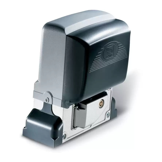
Page 4: Description Of Parts
4.3 Description of parts 1 - Top cover 2 - Settings casing 3 - Control board support 4 - Endstop fins 5 - ZBX74-78 electronic card 6 - Front cover to control panel 7 - Gearmotor release door 8 - Securing plate 9 - Securing bolt 10 - Securing screw plate 11 - Nut... -
Page 5: Standard Installation
5.2 Tools and materials Make sure you have all the tools and materials you will need for the installation at hand to work in total safety and compliance with the current standards and regulations. The following figure illustrates the minimum equipment needed by the installer. 5.3 Cable list and minimum thickness Length of cable Length of cable... - Page 6 5.5 Securing the plate and installing the assembly The following applications are only examples, as the space for installing the ratiomotor and accessories varies according to obstructions. It is thus up to the system installer to select the most suitable solution. - Dig a pit to the side of the gate (see measurements from diagram).
- Page 7 - To position the plate in relation to the rack please see the measurements on the diagram. Fill the form box with cement and wait for at least 24 hours for it to solidify. - Remove the form box, fi ll the pit around the cement block with soil. - Unbolt the nuts and washers from the bolts.
- Page 8 - Remove the cover from the gearmotor by loosening the side bolts, perforate the cable shafts using a screwdriver or a pair of scissors and position the gearmotor atop the plate. Careful! The electric cables must pass through the cable shafts. - Lift the gearmotor from the securing plate by about 5 to 10mm by using the threaded steel-levelling feet to allow any later adjustments between the pinion and the rack.
- Page 9 - Open and close the gate manually and register the pinion-to-rack distance using the threaded steel-levelling feet (for vertical adjusting) and the slotted holes (horizontal adjusting). This prevents the weight of the gate from bearing on the operator. Rack Rack Pinion Pinion Levelling feet...
- Page 10 5.6 Mounting the endstop fins Place the endstop fi ns onto the rack and secure them using a 3 mm Allen wrench. Their positioning limits the gate run. Note: the gate schould not slam against the mechanical stop, when opening or closing. Mechanical stop 5.7 Manually releasing the gearmotor - Insert the trilobed key into the lock, push it in and turn it clockwise ..
-
Page 11: Control Board
6 Control board 6.1 General description Use 230V AC to power the electronic card using the L-N Apposite trimmers regulate: terminals, at a max 50/60Hz frequency. - The automatic closing’s running time; - The partial opening; Use 24V to power the command devices and accessories. Careful! The accessories cannot exceed 20W of overall power. -
Page 12: Electrical Connections
6.3 Electrical connections Gearmotor, endstop and encoder Description of the standard electrical connections for left-hand installations 230V (AC) motor with encoder Orange Black Orange White Opening microswitch Closing microswitch Condenser Modifications to the electrical connections for right-hand installations White Invert the gearmotor (U-V) and (FA-FC) endstop phases. - Page 13 Warning devices Open-gate status light Movement fl ashing light (contact range: (Contact range: 230V - 25W 24V - 3W max) max) - Flashes during the gate’s - Signal that gate is open; opening and closing phases. turns off when gate is closed.
- Page 14 Safety devices photocells Dir/DeltaS (N.C.) contact for «re-open during closing phase» - Input for EN 12978 standard-compliant safety devices such as photocells. If contact is opened, while gate is closing, the gate inverts its direction. «partial stop» (N.C.) contact - Input for EN 12978 standard-compliant safety devices such as photocells.
-
Page 15: Function Selector
6.4 Function selector 1 2 3 4 5 6 7 8 9 1 0 1 2 3 4 DIP-SWITCH 1 ON - Automatic Closing - The automatic closing timer activates at the end of the opening gate run. The pre-set time is adjustable, and is in any case conditioned by the activation of any safety devices, and does not activate after a total safety “stop”... - Page 16 So as to fully meet the compliance requirements established by European Standards EN 12445 and EN 12453 on matters concerning maximum impact forces, BX-74/78 is set up for deceleration at 50 cm from the opening and closing endpoints. When installing all you need to do is...
-
Page 17: Activating The Radio Command
6.8 Motor torque limiter To vary the motor torque, move the shown faston (the one with the black wire) to one of the 4 positions: 1 min – 4 max. 1 2 3 4 7 Activating the radio command Antenna Possible output of the radio receiver’s second channel (N.O. - Page 18 Radio frequency card Only for the AF43S / AF43SM radi-frequency cards. - position jumper as shown depending on the series of transmitters you are using. Frequency Card Series Radio-frequency transmitters FM 26,995 AF130 FM 30.900 AF150 AM 26.995 AF26 AM 30.900 AF30 AM 433.92 AF43S / AF43SM...
- Page 19 8 Connecting two coupled gearmotors having a single control With two coupled gearmotors, you can command only the opening (by button and/or radio control): the gate will close only in automatic closing mode. • Coordinate the direction of travel of the two gearmotors , by modifying the motor's rotation (invert the cables on terminals FA-FC and U-V).
-
Page 20: Maintenance
10 Maintenance 10.1 Periodic maintenance Periodic maintenance to be carried out by the end-user is as follows: wipe clean the glass surface of the photocells; check that the safety devices work properly; remove any obstructions. We suggest checking the state of lubrication and tightness of the anchoring screws on the operator. -To check the efficiency of the safety devices, move an object in front of the photocells when gate is closing. -
Page 21: Extraordinary Maintenance
Periodic maintenance log for end-user (every 6 moths) Signature Date Notes 10.3 Extra-ordinary maintenance The following table serves to note down any extraordinary maintenance, repairs or improvements performed by specialised firms. N.B.: Any extraordinary maintenance must be performed by specialised technicians. Extra-ordinary maintenance log Installer’s stamp Operator name... -
Page 22: Declaration Of Conformity
CAME S.p.A. employs a UNI EN ISO 14001 certified and compliant environmental protection system at its plants, to ensure that environmental safeguarding. We ask you to keep protecting the environment, as CAME deems it to be one of the fundamental points of its market operations strategies, by simply following these brief guidelines when disposing: DISPOSING THE PACKING MATERIALS The packing components (cardboard, plastic, etc.) are solid urban waste and may be disposed of without any particular difficulty, by... - Page 24 Came S.p.A. Came S.p.A. Via Martiri Della Libertà, 15 Via Cornia, 1/b - 1/c 31030 Dosson di Casier Dosson di Casier 33079 Sesto al Reghena Sesto al Reghena Treviso Treviso - Italy Pordenone Pordenone - Italy (+39) 0422 4940 (+39) 0434 698111...
Need help?
Do you have a question about the BX-74 and is the answer not in the manual?
Questions and answers