Table of Contents
Advertisement
Advertisement
Table of Contents

Related Manuals for CAME BX-246


Summary of Contents for CAME BX-246
- Page 1 AUTOMATION 1 1 9 BU 50 EN FOR SLIDING GATES INSTALLATION MANUAL BX-246 English...
-
Page 2: Read Carefully
• This product should only be used for the purpose for which it was instructions • If the power cable is damaged, it must be replaced by the explicitly designed. Any other use is considered dangerous. CAME Cancelli manufacturer or the technical assistance service or by a person with a Automatici S.p.A. -
Page 3: Legend Of Symbols
For intensive or condominium use: max gate weight 600kg with max gate length 18 m. 3 Reference standards The company CAME cancelli automatici is ISO 9001 quality certified; it has also obtained the ISO 14001 environmental safeguarding certification. CAME engineers and manufactures all of its products in Italy. -
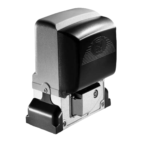
Page 4: Description Of Parts
4.3 Description of parts 1 - Top cover 2 - Settings casing 3 - Control board support 4 - Endstop fins 5 - ZD2 electronic card 6 - Front cover to control panel 7 - Gearmotor release door 8 - Securing plate 9 - Securing bolt 10 - Securing screw plate 11 - Nut... -
Page 5: Standard Installation
5.2 Tools and materials Make sure you have all the tools and materials you will need for the installation at hand to work in total safety and compliance with the current standards and regulations. The following figure illustrates the minimum equipment needed by the installer. 5.3 Cable list and minimum thickness Length of cable Length of cable... - Page 6 5.5 Securing the plate and installing the assembly The following applications are only examples, as the space for installing the ratiomotor and accessories varies according to obstructions. It is thus up to the system installer to select the most suitable solution. - Dig a pit to the side of the gate (see measurements from diagram).
- Page 7 - To position the plate in relation to the rack please see the measurements on the diagram. Fill the form box with cement and wait for at least 24 hours for it to solidify. - Remove the form box, fi ll the pit around the cement block with soil. - Unbolt the nuts and washers from the bolts.
- Page 8 - Remove the cover from the gearmotor by loosening the side bolts, perforate the cable shafts using a screwdriver or a pair of scissors and position the gearmotor atop the plate. Careful! The electric cables must pass through the cable shafts. - Lift the gearmotor from the securing plate by about 5 to 10mm by using the threaded steel-levelling feet to allow any later adjustments between the pinion and the rack.
- Page 9 - Open and close the gate manually and register the pinion-to-rack distance using the threaded steel-levelling feet (for vertical adjusting) and the slotted holes (horizontal adjusting). This prevents the weight of the gate from bearing on the operator. Rack Rack Pinion Pinion Levelling feet...
- Page 10 5.6 Mounting the endstop fins Place the endstop fi ns onto the rack and secure them using a 3 mm Allen wrench. Their positioning limits the gate run. Note: the gate schould not slam against the mechanical stop, when opening or closing. Mechanical stop 5.7 Manually releasing the gearmotor - Insert the trilobed key into the lock, push it in and turn it clockwise ..
-
Page 11: Control Board
6 Control board 6.1 General description Use 230V AC to power the electronic card using the L-N - The automatic closing’s running time; terminals, at a max 50/60Hz frequency. - The partial opening; - The amperometric device’s detection sensitivity, in both normal Use 24V to power the command devices and accessories. -
Page 12: Electrical Connections
3 4 5 6 7 8 9 10 6.3 Electrical connections Gearmotor, endstop and encoder Description of the standard electrical connections for left-hand installations Black Orange White Orange 24 V (DC) motor Opening microswitch Closing microswitch with encoder Modifications to the electrical connections for right-hand installations White Invert the gearmotor (U-V) and (FA-FC) endstop phases. - Page 13 Power supply for accessories Cable lug with bolt and washer for connecting to earth. Terminals for powering the following accessories: - 24V AC normally; - 24V DC when the emergency batteries are working; Maximum allowed power: 35W 230V (AC) Power, 50/60Hz frequency Warning devices Movement fl...
- Page 14 Safety devices DIR / DELTAS photocells «partial stop» (N.C.) contact - Input for EN 12978 standard-compliant safety devices such as photocells. Gate stops if moving and automatically shuts (if this functions has been selected). DIR / DELTAS photocells (N.C.) contact for «re-open during closing phase» - Input for EN 12978 standard-compliant safety devices such as photocells.
- Page 15 DF with DFI con- «Open while closing»(N.C.) contact nections monitor - input for EN 12978 compliant safety card devices such as sensitive edges. During gate closing, opening the contact causes inversion of movement until gate is fully open; if not used, short circuit contact 2-C7.
-
Page 16: Function Selector
7 Function selector DIP-SWITCH Default Setting 1 ON - Automatic Closing - The automatic closing timer activates at the end of the opening gate run. The pre-set time is adjustable, and is in any case conditioned by the activation of any safety devices, and does not activate after a total safety “stop” or during a blackout. -
Page 17: Warning Led
9 Warning Led Led PROG Led PWR Led 1 Led C8 Led 3p Led 7 Led C1 Led C3 Led C7 LIST WARNINGS OF THE COMMAND AND SAFETY DEVICES’ CONTROL LEDs: - «PROG» Red Led. Normally off . When the transmitter is activating, it turns on or fl ashes. - «PWR»... - Page 18 10 Programmation to save gate-run and decelerations adjustments Do the adjustment by making the operator execute a complete opening/closing manoeuvre The control board automatically registers the gate-run adjustments with opening and closing decelerations. To save the adjustment, position dip 6 in ON and press CH1 button until the signalling led stays on. Re-position the dip in OFF Lit LED DIP 6 to OFF...
- Page 19 11 Activating the radio control Connect the antenna’s RG58 cable. Cut off the main power supply, and remove any batteries. Fit the AF board onto the electronic board. The electronic board recognizes the AF board only when the operator is powered up again. Keep the CH1 button on the electronic board pressed: the warning LED flashes.
- Page 20 12 Connecting two coupled gearmotors having a single control With two coupled gearmotors, you can command only the opening (by button and/or radio control): the gate will close only in automatic closing mode. • Coordinate the direction of travel of the two gearmotors , by modifying the motor's rotation (invert the cables on terminals FA-FC and M-N).
-
Page 21: Safety Instructions
13 Safety instructions Important safety instructions This product must only be employed for its originally intended use. Any other use is wrong and potentially dangerous. The manufactu- rer cannot be held liable for any damages resulting from wrongful, erroneous or negligent uses. Avoid working close to the hinges or other moving mechanical parts. -
Page 22: Extraordinary Maintenance
Periodic maintenance log for end-user (every 6 moths) Signature Date Notes 14.2 Trouble shooting MALFUNCTIONS POSSIBLE CAUSES CHECK AND REMEDIES The gate will not • There is no power • Check that the power is up open nor close • The gearmotor is in release mode and the release door is open •... -
Page 23: Declaration Of Conformity
CAME CANCELLI AUTOMATICI S.p.A. employs a UNI EN ISO 14001 certified and compliant environmental protection system at its plants, to ensure that environmental safeguarding. We ask you to keep protecting the environment, as CAME deems it to be one of the fundamental points of its market operations strategies, by simply following these brief guidelines when disposing: DISPOSING THE PACKING MATERIALS The packing components (cardboard, plastic, etc.) are solid urban waste and may be disposed of without any particular difficulty, by simply... - Page 24 HR • Za sve dodatne informacije o poduzeću, proizvodima i tehničkoj podršci: UK • Для отримання будь-якої іншої інформації про компанію, продукцію та технічну підтримку: www. came.com www. came.com CAME Cancelli Automatici S.p.a. CAME Cancelli Automatici S.p.a. Via Martiri Della Libertà, 15 31030 Dosson Di Casier...
Need help?
Do you have a question about the BX-246 and is the answer not in the manual?
Questions and answers