Table of Contents
Advertisement
Available languages
Available languages
Quick Links
SUPER 6000
Operatore
Operateur
Operator
Torantrieb
Operador
SUPER 6000
SUPER 6000 ICE
Die korrekte Bedienung des Bedieners ist nur gewährleistet, wenn er von einem RIB-Bedienpanel verwaltet wird
ITALIANO pag. 05 / FRANÇAIS pag. 17 / ENGLISH page 29/ DEUTSCH pag. 41 / ESPAÑOL pag. 53
Alimentazione
Peso max cancello
Alimentation
Poids maxi portail
Power Supply
Max gate weight
Stromspannung
Max Torgewicht
Alimentacion
Peso máx verja
400V 3~50/60Hz
6000 kg / 13228 lbs
Il corretto funzionamento dell'operatore è garantito solo se viene gestito da un quadro di comando RIB
Le bon fonctionnement de l'opérateur n'est garanti que s'il est géré par un panneau de contrôle RIB
The correct operation of the operator is guaranteed only if it is managed by a RIB control panel
El funcionamiento correcto del operador solo está garantizado si está gestionado por un panel de control RIB
con / avec / with / mit
L1/R4-CRX
Spinta max
Poussée maxi
Couple maxi
Max Thrust
Max Schubkraft
Max. Drehmoment
Max Empuje
900 kg / 1980 lbs
1
Vedere pagina 15
Voir page 27
See page 39
Siehe Seite 51
Ver página 63
Coppia max
Codice
Code
Max torque
Code
Code
Coppia max
Codigo
AA38004
405 Nm
AA38006
Advertisement
Table of Contents

Related Manuals for RIB SUPER 6000


Summary of Contents for RIB SUPER 6000
- Page 1 Le bon fonctionnement de l’opérateur n’est garanti que s’il est géré par un panneau de contrôle RIB The correct operation of the operator is guaranteed only if it is managed by a RIB control panel Die korrekte Bedienung des Bedieners ist nur gewährleistet, wenn er von einem RIB-Bedienpanel verwaltet wird El funcionamiento correcto del operador solo está...
- Page 2 2° - En ce qui concerne la section et le type des câbles, RIB conseille d’utiliser un câble de 2° - Per la sezione ed il tipo dei cavi la RIB consiglia di utilizzare un cavo di tipo H05RN-F con type H05RN-F ayant une section minumum de 1,5 mm 2 et de toute façon, s’en tenir à...
- Page 3 Kontaktöffnung von 3 mm), der ein von den internationalen Normen 2° - For the section and the type of the cables RIB advices to use a cable of H05RN-F type anerkanntes Konformitätszeichen besitzt. Solch ein Geraet muss vor Vandalismus with 1,5 sqmm minimum section and, however, to keep to the IEC 364 and installation geschuetzt werden (z.B.mit einen Schluesselkatsten in einem Panzergehaeuse).
- Page 4 L’eliminazione dei materiali va fatta rispettando le norme vigenti. Non gettate il vostro 2° - Para la sección y el tipo de los cables, RIB aconseja utilizar cables de tipo H05RN-F con apparecchio scartato, le pile o le batterie usate nei rifiuti domestici. Avete la responsabilità di sección mínima de 1,5 mm 2 e igualmente atenerse a la norma IEC 364 y a las normas de...
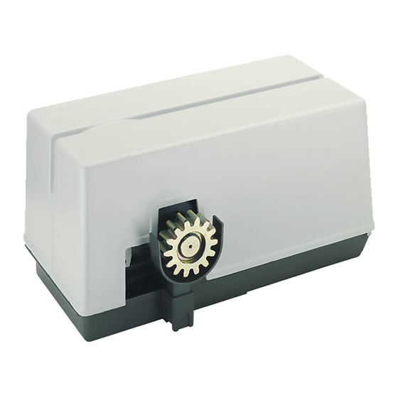
- Page 5 CARATTERISTICHE TECNICHE SUPER 6000 Operatore irreversibile per cancelli industriali scorrevoli con peso massimo di 6000 kg. SUPER 6000 è adatto ad un uso intensivo ed è dotato di una frizione oleodinamica di facile taratura, Peso max cancello 6000 insensibile alle diverse temperature, che ammorbidisce le partenze, gli arresti e le inversioni di marcia Velocità...
- Page 6 INSTALLAZIONE SUPER 6000 CONTROLLO PRE-INSTALLAZIONE - IL CANCELLO DEVE MUOVERSI SENZA ATTRITI - N.B. È obbligatorio uniformare le caratteristiche del cancello alle norme e leggi vigenti. La porta può essere automatizzata solo se in buono stato e se rispondente alla norma EN 12604.
-
Page 7: Manutenzione
FISSAGGIO MOTORE E CREMAGLIERA SUPER 6000 è accessoriato di piastra da cementare al suolo e ne viene bloccato tramite le 4 viti TE 14x45 in dotazione con una chiave esagonale n°22. La cremagliera va fissata a una certa altezza rispetto alla piastra di fissaggio del motore. -
Page 8: Collegamenti Elettrici
COLLEGAMENTI ELETTRICI L1/R4-CRX cod. ABL1/R4RX Manuali online interattivi COMUNE Manuels interactifs en ligne STOP Interactive online manuals FOTOCELLULA 1 Interaktive Online-Handbücher FOTOCELLULA 2 ENCODER Manuales interactivos en línea. COSTA 1 COSTA 2 COMUNE FINECORSA CHIUSURA FINECORSA APERTURA COMUNE OROLOGIO PEDONALE COMANDO SINGOLO CHIUDE APRE... - Page 9 RADIO Connettore per modulo radio ACG8069 COM A+ Comune dei contatti / Positivo 24 Vdc RADIO Connettore per radio ricevitore rib ad innesto con alimentazione a 24 Vdc. B.I.O. Ingresso contatto orologio (NA) Antenna radio 433 MHz PED. Contatto comando apertura pedonale (NA) PROG.
- Page 10 B - SETTAGGI START Comando impulso singolo (verde) CLOSE Comando Chiude (verde) OPEN Comando Apre (verde) DIP 1 (ON) - CONTROLLO PER MANUTENZIONE (PAG. 13) DIP 2 (ON) - PROGRAMMAZIONE TEMPI (PUNTO C) PROBE DIP 2-1 PROGRAMMAZIONE TEMPI APERTURA PEDONALE (PUNTO D) NON DISPONIBILE DIP 1-2 MEMORIZZAZIONE/CANCELLAZIONE CODICI RADIO COMANDO APERTURA TOTALE (DIP 1 ON seguito da DIP 2 ON) (PUNTO E)
- Page 11 DIP 6 OFF => Esegue l’apertura a cancello chiuso. Se azionato durante il movimento di Tramite App RIB GATE è possibile configurare il funzionamento di questo relé a piacere. apertura non ha effetto. Se azionato a cancello aperto lo chiude e durante la La programmazione può...
- Page 12 le colonnine di supporto alle fotocellule al morsetto A - per proteggere le fotocellule da fonti SIGNAL - SPIA DI CANCELLO APERTO a 24Vdc (COM A+/SIGNAL-) di disturbo. Ha il compito di segnalare quando il cancello è aperto, parzialmente aperto o comunque non Fate attenzione a non creare corto circuiti quando le fasi di alimentazione sono invertite! chiuso totalmente.
- Page 13 il ponticello fra COM A+ e EDGE 1/EDGE 2) DL13 blu acceso Alcune funzioni sono abilitate tramite smartphone, verificare quindi tramite smartphone lo stato della scheda in quanto lo stato dei dip/ trimmer potrebbe essere non veritiero. Sulla scheda esistono dei fusibili ripristinabili che intervengono in caso di corto circuito interrompendo l'uscita a loro assegnata.
- Page 14 DIFETTO SOLUZIONE Sulla scheda esistono dei fusibili ripristinabili che intervengono in caso di corto circuito interrompendo l'uscita a loro assegnata. A fronte di una ricerca guasti si consiglia di scollegare tutti i connettori estraibili e di inserirli Dopo aver effettuato i vari collegamenti e aver dato tensione, tutti i led sono spenti. uno a volta in modo da identificare più...
- Page 15 APP8054 Scheda APP+ APP8050 Scheda APP per gestire la centrale di comando per gestire la centrale di comando tramite Bluetooth tramite Bluetooth APP8064 Modulo Wi-Fi per Scheda APP8066 Modulo RJ45 per Scheda APP+ APP+ per gestire la centrale tramite rete per gestire la centrale tramite rete Wi-Fi locale (WLAN) dati locale (LAN)
- Page 16 RED permette la realizzazione di un impianto con coste fissate anche sull’anta in movimento senza l’adozione di sistemi raccogli cavo. È conforme alla norma EN13849-1:2007 e congiuntamente ad un quadro elettronico RIB è un dispositivo di protezione di Classe 2.
- Page 17 SCHÉMA DÉTAILLÉ DE L’INSTALLATION A - Operateur SUPER 6000 B - Photocellules p/protec. externe C - Cremaillere M6 D - Selecteur E - Antenne radio F - Signal electrique H - Poteau zingué p/cellule ne I - Photocellules p/protection interne L - Barre palpeuse mécanique fixé...
- Page 18 INSTALLATION SUPER 6000 CONTRÔLE PRÉ-INSTALLATION !! LE PORTAIL DOIT SE DÉPLACER SANS FROTTER !! N.B.: Il est impératif d’uniformiser les caractéristiques du portail avec les normes et les lois en vigueur. La porte peut être automatisée seulement si elle est en bon état et qu’elle est conforme à...
-
Page 19: Entretien
INSTALLATION DU MOTOR E DE LA CREMAILLERE SUPER 6000 est doté d’une plaque à sceller dans le sol et il est bloqué au moyen des 4 vis H 14x45 en dotation au moyen d’une clé 6 pans n°22. La crémaillère doit être fixée à une certaine hauteur par rapport à la base du moteur. -
Page 20: Branchements Électriques
BRANCHEMENTS ÉLECTRIQUES L1/R4-CRX code ABL1/R4RX Manuali online interattivi COMMUN Manuels interactifs en ligne STOP Interactive online manuals PHOTOCELLULES 1 Interaktive Online-Handbücher PHOTOCELLULES 2 ENCODER CORDON 1 Manuales interactivos en línea. CORDON 2 COMMUN FIN FERMETURE FIN OUVERTURE COMMUN HORLOGE PIETON COMMANDE UNIQUE FERMETURE OUVERTURE... - Page 21 IEC 34-1) LA FICHE AVEC DIP 13 EN POSITION Les protections électriques, présentes sur la ligne “ON”. d’alimentation du moteur SUPER 6000 pourraient ne pas suffire à garantir la protection contre les PROG surcharges. En effet, si les conditions de ventilation empirent, le moteur chauffe, mais les conditions électriques ne varient nullement empêchant ainsi...
- Page 22 B - RÉGLAGES DL14 Encodeur active (rosso) DL15 Commande PROG et RADIO sur molex (vert) DIP 1 CONTRÔLE D’ENTRETIEN (PAGE 25) (ON) B.I.O. Commande de horloge (vert) DIP 2 PROGRAMMATION DE LA DURÉE (ON) (POINT C) PED. Commande ouverture piétonne (vert) DIP 2-1 PROGRAMMATION DES LAPS DE TEMPS D’OUVERTURE POUR PIÉTONS (DIP 2 ON suivi de START Commande impulsif...
- Page 23 S’il est actionné à portail ouvert piéton, il Grâce à l’application RIB GATE, il est possible de configurer le fonctionnement de ce relais à le ferme. Si actionné pendant la fermeture, il rouvre le portail.
- Page 24 (avec reprise du mouvement inverse après une seconde même si ces dernières CLIGNOTANT (code ACG7072) de 40 W maximum. demeurent occupées). FONCTION PRÉ-CLIGNOTEMENT ATTENTION: Si la led du récepteur reste allumée, il est possible qu’ il y ait des perturbations DIP 5 OFF =>...
- Page 25 Après avoir effectué tous les raccordements en suivant attentivement le schéma et avoir positionné le portail en position intermédiaire, vérifier l’allumage correct des leds rouges DL6, DL7, DL8, DL9 et DL10. Si les leds ne s’allument pas, en maintenant toujours le portail en position intermédiaire, vérifier les points ci-après et éventuellement remplacer les composants qui ne fonctionnent pas.
- Page 26 TABLEAU RÉCAPITULATIF ALARMES VISUELLES ET SONORES SIGNALISATIONS EN COURS DE PROGRAMMATION ÉVÉNEMENT ÉTAT BUZZER ÉTAT CLIGNOTEUR ÉTAT LED DL1 DIP 1 ON (mode homme mort) Éteint Éteint Clignote 250 ms ON/OFF Ou panne d'une sécurité DIP 2 ON (programmation course totale) Éteint Éteint Clignote 500 ms ON/OFF...
- Page 27 MODULE RADIO 433MHz EMETTEUR RADIO SUN cod. ACG8069 SUN 2CH cod. ACG6052 SUN 4CH cod. ACG6054 SUN CLONE 2CH cod. ACG6056 SUN CLONE 4CH cod. ACG6058 SUN-PRO 2CH cod. ACG6210 SUN-PRO 4CH cod. ACG6214 APP8054 Carte APP+ APP8050 Carte APP pour gérer le tableau de contrôle via pour gérer le tableau de contrôle via Bluetooth 4.2...
- Page 28 RED permet la réalisation d’une installation avec barres palpeuses fixées également sur le battant en mouvement sans l’adoption de systèmes d’assemblage de câbles. Il est conforme à la norme EN13849-1:2007 et associé à un tableau électronique RIB, il est un dispositif de protection de Classe 2.
-
Page 29: System Layout
Irreversible operating devices for sliding gates with a maximum weight of 6000 kg / 13.200 lbs. Normative cycles n° 300-95s/2s SUPER 6000 is equipped with an easily adjusted hydraulic clutch which will not be affected by the various temperature changes. This softens the starts, stops and reversals of heavy gates. Power supply 380V 3~ 60Hz Its self-braking motor is able to limit gate inertia during the stopping phase. - Page 30 INSTALLATION SUPER 6000 CHECKING BEFORE THE INSTALLATION !! THE GATE SHALL MOVE FRICTIONLESS !! N.B.: Gate features must be uniformed with the standards and laws in force. The door/gate can be automated only if it is in a good condition and its conditions comply with the EN 12604 norm.
-
Page 31: Maintenance
MOTOR AND RACK INSTALLATION SUPER 6000 has a plate to be cemented to the ground and is locked in place by the four supplied 14x45 hex bolts using a N° 22 setscrew wrench. The rack must be fixed at a certain height with respect to the motor base. -
Page 32: Electric Connections
ELECTRIC CONNECTIONS L1/R4-CRX code ABL1/R4RX Manuali online interattivi COMMON Manuels interactifs en ligne STOP PHOTOCELL 1 Interactive online manuals PHOTOCELL 2 ENCODER Interaktive Online-Handbücher EDGE 1 Manuales interactivos en línea. EDGE 2 COMMON LIMIT SWITCH CLOSE LIMIT SWITCH OPEN COMMON TIMER PEDESTRIAN SINGLE COMMAND... - Page 33 INNER THERMAL OVERLOAD CUT-OUT SWITCHES PROG (per CEI 2-3/IEC 34-1) The electrical protections on the SUPER 6000 motor power line may not be sufficient to protect against overloads. If the cooling conditions worsen, the motor overheats but the electrical conditions do not change, which inhibits line protections.
- Page 34 POINT B - SETTINGS PROBE DIP 1 MAINTENANCE CHECK (See Page 36) IS NOT AVAILABLE DIP 2 PROGRAMMING (See Point C) DIP 2-1 PROGRAMMING OF PEDESTRIAN OPENING (See Point D) POINT C - TIMES PROGRAMMING DIP 1-2 SAVE/DELETE RADIO CODES FOR COMPLETE OPENING (DIP 1 ON followed by DIP 2 ON) (POINT E) N.B .: During the programming the safety functions Coast, Photocells and Stop button are DIP 1-3...
- Page 35 Indication is visible only when gate is stationary. This function is useful during peak hours, when vehicle traffic is slow (e.g. entry/exit of 1 - Set DIP 1 to ON and then DIP 2 to ON. workers, emergencies in parking or residential areas and, temporarily, for moving operations). 2 - The LED DL12 flashes green 6 times when the memory is full (1000 codes).
- Page 36 The STOP button stops the gate during any operation. - Current available on radio connector 200mA 24Vdc If held when the gate is fully open (or partially when using the pedestrian control) automatic - ALL THE PUSH BUTTONS, INPUTS AND COMMANDS CONNECTED TO THE CONTROL BOARD MUST BE closing is temporarily deactivated (if activated by the TCA trimmer and LED DL11 on).
- Page 37 TABLE SUMMARISING VISUAL AND SOUND ALARMS SIGNALS DURING PROGRAMMING SEQUENCE EVENT BUZZER STATUS FLASHER STATUS DL1 LED STATUS DIP 1 ON (hold-to-run mode) Flashes ON/OFF 250 ms Or failure of a safety device DIP 2 ON (full stroke programming) Flashes ON/OFF 500 ms DIP 2 ON >...
- Page 38 ACCESSORIES - For the connections and the technical data of the optional equipments follow the relevant handbooks. PLATE TO BE CEMENTED MODULE 6 RACK with CATAPHORESIS treatment, right angle in 2 m - 6,56 feet bars. code ACS9090 code ACG8105 RADIO TRANSMITTER SUN RADIO MODULE 433MHz SUN 2CH...
- Page 39 ACCESSORIES - For the connections and the technical data of the optional equipments follow the relevant handbooks. APP8050 APP card APP8054 APP+ card to manage the control panel using to manage the control panel using Bluetooth 4.2 transmission Bluetooth 4.2 transmission APP8064 Wi-Fi module for APP+ card APP8066 RJ45 module for APP+ card to manage the control panel using the...
- Page 40 RED allows to make a system made with edges fixed to the moving shutter without having to use cable sleeving systems. It complies with EN13849-1:2007 Standard, if installed with an RIB Electronic Board it is a Class-2 Device. code ACG6202...
- Page 41 ANLAGEN LAY-OUT A - Torantrieb SUPER 6000 B - Photozelle Toraussenseitig C - Zahnstange M6 D - Schlusselschalter E - Antenne F - Blinkleuchte H - Verzinkte Metallsäule als Photozellentrager I - Photozelle - Torinnenseitig L - Sicherheitskontaktleiste auf dem Schiebetor...
- Page 42 INSTALLATION SUPER 6000 VOR DER MONTAGE AUSZUFÜHRENDE ÜBERPRÜFUNGEN !! DAS TOR MUSS REIBUNGSFREI LAUFEN !! ANMERKUNG: Es ist erforderlich, die Charakteristiken des Tors an die geltenden Normen und Gesetze anzupassen. Das Tor kann nur automatisch Angeschlossen werden, wenn es in einem einwandfreien Zustand ist und der EN12604 entspricht.
-
Page 43: Wartung
E 100 EXTRA / MOBIL ATF 2000 / CHEVRON OCTURBINE OIL 11 / GULF PARAMOUNT 35. EINSTELLUNG DER KEILRIEMEN SUPER 6000 hat zwei Keilriemen, mit denen die Bewegung von Motor/Kupplung auf den Antrieb übertragen wird. Die Spannung dieser Keilriemen läßt sich ändern, indem man die Höhe von Motor und Kupplung ändert. - Page 44 ELEKTROANSCHLÖÜSSE L1/R4-CRX Kode ABL1/R4RX Manuali online interattivi GEMEINSAMER ERDUNGSKONTAKT Manuels interactifs en ligne STOP Interactive online manuals FOTOZELLE 1 Interaktive Online-Handbücher ENCODER FOTOZELLE 2 Manuales interactivos en línea. KONTAKTLEISTE 1 KONTAKTLEISTE 2 GEMEINSAMER ERDUNGSKONTAKT ENSCHALTER SCHLIESSEN ENSCHALTER ÖFFNEN GEMEINSAMER ERDUNGSKONTAKT ZEITGESTUERTE ÖFFNUNG FUSSGÄNGER EINZELIMPULS...
- Page 45 Negative Ladung für die Speisung der Zubehöre zu 24Vdc A+ TEST Positive Ladung für die Speisung für Fotozellen Selbstkontrolle RADIO Verbinder für Radio-Modul ACG8069 Verbinder für Radioempfänger RIB Steckverbindung mit Speisung COM A+ Gemeinsame erdungskontakte / Positive 24 Vdc RADIO zu 24Vdc B.I.O.
- Page 46 B - EINSTELLUNGEN PED. Fußgänger Öffnungsbefehl (NO) (Grün) START Einzelimpulsbefehl (NO) (Grün) DIP 1 WARTUNGSÜBERPRÜFUNG (SIEHE SEITE 49) CLOSE Befehl Schließen (NO) (Grün) DIP 2 ZEITPROGRAMMIERUNG (ON) (PUNKT C) OPEN Befehl Öffnung (NO) (Grün) DIP 2 - 1 ZEITPROGRAMMIERUNG ÖFFNUNG FUSSGÄNGER (DIP 2 ON GEFOLGT VON DIP 1 ON) (PUNKT D) PROBE DIP 1-2...
- Page 47 * Die Fernsteuerungsverwaltung kann nur mit der RIB GATE-App aktiviert werden. R-AUX arbeitet normalerweise 3 Minuten lang als Zusatzbeleuchtung. FUNKTIONSWEISE DER SICHERHEITSEINRICHTUNGEN Über die RIB GATE-App kann der Betrieb dieses Relais wie gewünscht konfiguriert werden. Die Programmierung kann nur bei stehendem Tor erfolgen. FOTOZELLE (COM A+/PHOT 1, COM A+/PHOT 2) 1 - Stellen Sie DIP 1 auf ON, DIP 2 auf ON und DIP 3 auf ON.
- Page 48 ÜBERWACHUNG DER FOTOZELLEN (A+ TEST/A-) SIGNAL - 24Vdc ANZEIGELEUCHTE TOR GEÖFFNET (COM A+/SIGNAL-) Den Fotozellensender an A+ TEST/A- anschließen und DIP 7 auf ON stellen. Signalisiert, wenn das Tor OFFen, teilweise OFFen oder nicht vollständig geschlossen ist. Es wird Die Überwachung besteht aus einem Funktionstest der Fotozelle vor jeder Bewegung. nur ausgeschaltet, wenn das Tor vollständig geschlossen ist.
- Page 49 DL7 oder DL8 AUS Fotozellen beschädigt (Falls die Rippe nicht angeschlossen ist einen Überbrückungsdraht zwischen COM A+ und PHOTO 1/PHOTO 2 legen) DL9 oder DL10 AUS Konktatleisten Schaden (Falls die Rippe nicht angeschlossen ist einen Überbrückungsdraht zwischen COM A+ und EDGE 1/EDGE 2 legen) DL13 blau AUF Einige Funktionen sind über das Smartphone aktiviert.
- Page 50 ÜBERSICHTSTABELLE DER VISUELLEN UND AKUSTISCHEN ALARMEN SIGNALISIERUNGEN WÄHREND DER PROGRAMMIERPHASE EREIGNIS STATUS BUZZER STATUS BLINKLEUCHTE STATUS LED DL 1 DIP 1 ON (“befehl gedrückt gehalten”-modus) Abgeschaltet Abgeschaltet Blinkt 250 ms ON/OFF oder defekt einer sicherheitsvorrichtung DIP 2 ON (laufprogrammierung ganz) Abgeschaltet Abgeschaltet Blinkt 500 ms ON/OFF...
- Page 51 FERNSENDER SUN RADIO-MODUL 433MHz SUN 2CH Kode ACG6052 SUN 4CH Kode ACG6054 Kode ACG8069 SUN CLONE 2CH Kode ACG6056 SUN CLONE 4CH Kode ACG6058 SUN-PRO 2CH Kode ACG6210 SUN-PRO 4CH Kode ACG6214 APP8050 APP-Karte APP8054 APP+-Karte um das Steuerung mit Bluetooth um das Steuerung mit Bluetooth 4.2-Übertragung zu verwalten 4.2-Übertragung zu verwalten...
- Page 52 RED erlaubt die Realisierung einer Anlage mit Kontaktleisten, die auch auf dem sich bewegenden Tor angebracht sein können, ohne dass man Kabelsammelsysteme benötigt. Entspricht der Norm EN13849-1:2007 und in Verbindung mit einer RIB - Schalttafel stellt es eine Schutzvorrichtung der Klasse 2 dar.
- Page 53 Peso máx. verja 6000 Operadores irreversibles para verjas correderas con un peso máximo de 6000 kg. SUPER 6000 se puede utilizar para uso intensivo, tiene embrague oleodinàmico con taradura fàcil, Velocidad de arrastre 0,160 insensible a las diferentes temperaturas, esfuma las salidas, las paradas y las inversiones de sentido...
- Page 54 INSTALACIÓN SUPER 6000 CONTROL PRE-INSTALACIÓN ¡¡LA VERJA TIENE QUE MOVERSE SIN ROCES!! IMPORTANTE: Es obligatorio uniformar las características de la verja a las normas y leyes en vigor. La puerta puede ser automatizada sólo si se encuentra en buen estado y responde a la norma EN 12604.
-
Page 55: Mantenimiento
ANCLAJE MOTOR Y CREMALLERA SUPER 6000 tiene como accessorio una placa que cementar, bloqueada por 4 tornillos TE 14x45 ya en dotaciòn con llave exagonal no. 22. La cremallera se tiene que anclar a una determinada altura respecto al soporte del motor. -
Page 56: Conexiones Eléctricas
CONEXIONES ELÉCTRICAS L1/R4-CRX cod. ABL1/R4RX Manuali online interattivi COMÚN Manuels interactifs en ligne STOP Interactive online manuals FOTOCÉLULA 1 FOTOCÉLULA 2 ENCODER Interaktive Online-Handbücher BANDA 1 Manuales interactivos en línea. BANDA 2 COMÚN FINAL CIERRE FINAL APERTURA COMÚN RELOJ PEATONAL SOLO COMANDO CIERRE ABRE... - Page 57 2-3 / IEC 34-1) ES OBLIGATORIO PROGRAMAR LA Las protecciones electricas ahora exhistentes en la PLACA CON DIP 13 EN POSICION ON. linea de alimentaciòn del motor SUPER 6000, pueden PROG ser insuficientes para la completa protecciòn en caso de sobrecargas.
- Page 58 B - AJUSTES B.I.O. Mando reloj (NA) (verde) PED. Mando de apertura peatonal (NA) (verde) DIP 1 CONTROL DE MANTENIMIENTO (ON) (PÁGINA 61) START Mando de impulso unico (NA) (verde) DIP 2 PROGRAMACIÓN DE LOS TIEMPOS (ON) (PUNTO C) CLOSE Mando de cierre (NA) (verde) DIP 2-1 PROGRAMACIÓN DE LOS TIEMPOS DE APERTURA PEATONAL (DIP 2 ON seguido por DIP 1 OPEN Mando de apertura (NA)
- Page 59 R-AUX normalmente funciona como una luz de cortesía durante 3 minutos. peatonal. A través de la aplicación RIB GATE es posible configurar la operación de este relé como se DIP 6 ON => Ejecute un mando cíclico de órdenes abre-stop-cierra-stop-abre etc.
- Page 60 después de que las fotocélulas se liberan), como en cierre (restableciendo el seguridad por un corecto funcionamiento. movimiento inverso sólo después de que las fotocélulas se liberan). DIP 4 ON => Con la cancela cerrada, si se interpone un obstáculo delante del rayo de las ALARMAS VISUALES Y ACÚSTICAS fotocélulas y se ordena la apertura, la cancela se abre (durante la apertura las fotocélulas no intervendrán).
-
Page 61: Resolución De Problemas
3 - Al final, coloque nuevamente el DIP 1 en OFF. El LED DL1 se apaga, indicando la salida del control. Si el motor no funciona durante esta comprobación, verifique las conexiones y su condensador. Si el motor funciona correctamente, verifique los dispositivos de seguridad. RESOLUCIÓN DE PROBLEMAS Después de haber efectuado todas las conexiones siguiendo atentamente el esquema y haber posicionado el portón en posición intermedia, verifique el correcto encendido de los led rojos... - Page 62 TABLA SINÓPTICA DE LAS ALARMAS VISUALES Y ACÚSTICAS SEÑALIZACIONES EN FASE DE PROGRAMACIÓN EVENTO ESTADO DE BUZZER ESTADO DE L'INTERMITENTE ESTADO LED DL1 DIP 1 ON (modo persona presente) Apagado Apagado Parpadea 250 ms ON/OFF O bien avería de un seguro (modo funciona siempre) DIP 2 ON (programación carrera total) Apagado Apagado...
- Page 63 MÓDULO RADIO 433MHz TELEMANDO SUN SUN 2CH cód. ACG6052 SUN 4CH cód. ACG6054 cod. ACG8069 SUN CLONE 2CH cód. ACG6056 SUN CLONE 4CH cód. ACG6058 SUN-PRO 2CH cód. ACG6210 SUN-PRO 4CH cód. ACG6214 APP8054 Tarjeta APP+ APP8050 Tarjeta APP para administrar la unidad de control para administrar la unidad de control a través de Bluetooth 4.2 a través de Bluetooth 4.2...
- Page 64 RED permite realizar una instalación con costas colocadas incluso sobre la hoja en movimiento sin la adopción de sistemas recoge cables. Conforme a la norma EN13849-1:2007. Unido a un cuadro electrónico RIB es un dispositivo de protección de Clase 2.
- Page 65 COLLEGAMENTI FOTOCELLULE - CONNEXIONS PHOTOCELLULE - PHOTOCELLS CONNECTIONS FOTOZELLEN VERBINDUNGEN - CONEXIONES FOTOCÉLULAS 4 fotocellule FIT SLIM / FIT SYNCRO con autotest e sincronizzatore del segnale infrarosso 2 fotocellule FIT SLIM, FIT SYNCRO con autotest 4 photocellules FIT SLIM / FIT SYNCRO avec autotest et synchroniseur de signal infrarouge 2 photocellules FIT SLIM, FIT SYNCRO avec autotest 4 FIT SLIM / FIT SYNCRO photocells with self-test and infrared signal synchronizer 2 photocells FIT SLIM, FIT SYNCRO with self-test...
- Page 66 COLLEGAMENTI FOTOCELLULE - CONNEXIONS PHOTOCELLULE - PHOTOCELLS CONNECTIONS FOTOZELLEN VERBINDUNGEN - CONEXIONES FOTOCÉLULAS 4 fotocellule NOVA sincronizzate con autotest 4 photocellules NOVA synchronisées avec autotest 4 NOVA photocells synchronized with self-test 4 NOVA Photozellen synchronisiert mit Selbstkontrolle 4 fotocélulas NOVA sincronizadas con autotest PHOT1 PHOT2 A+ TEST COM A+...
- Page 67 Corona bronzo con mozzo ghisa Z=42 CME8130 Puleggia doppia ACG1080 Chiave per serratura carter CME3011 Flangetta posteriore CME9008 Vite senza fine SUPER 6000 ACG8105 Piastra da interrare SUPER 6000 CME3015 Flangia coperchio CMO1035 Motore SUPER 6000 400V/50Hz 3P BA01049 Gruppo riduttore completo...
- Page 68 R.I.B. S.r.l. - Via Matteotti, 162 - 25014 Castenedolo - Brescia - Italy Tel. ++39.030.2135811 - www.ribind.it - ribind@ribind.it Apparecchio modello : Oggetto della dichiarazione : SUPER 6000 Modèle d'appareil : Objet de la déclaration : Apparatus model : Object of the declaration :...
Need help?
Do you have a question about the SUPER 6000 and is the answer not in the manual?
Questions and answers