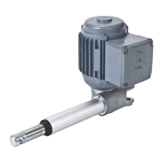
Summary of Contents for Ewellix CAT 33
- Page 1 I N S TA L L AT I O N , O P E R AT I O N A N D M A I N T E N A N C E M A N UA L CAT 33, 33H...
-
Page 3: Table Of Contents
Contents 1.0 General information ............4 1.1 Information on this manual ..........4 1.2 Explanation of symbols and signal words ......4 2.0 Important safety information ........5 3.0 Intended use ..............6 3.1 Duty Factors ..............6 3.1.1 DC Versions .............6 3.1.2 AC Versions ..............7 3.2 Requirements for correct installation ......8 4.0 Available versions ............9 5.0 Optional equipment ............9... -
Page 4: General Information
C AT 3 3 , 3 3 H a n d 3 2 B 1.0 General information DANGER 1.1 Information on this Indicates a dangerous situation, which will lead to death or serious personal manual injury, if the precautionary measures are ignored. -
Page 5: Important Safety Information
Modification of the actuator is not al- lowed in any way. Any modification will void the warranty and could create a safety hazard. Ewellix disclaims any and all liability or responsibility for the modified product and for... -
Page 6: Intended Use
WARNING If temperture is permitted to raise uncontrolled the actuator can eventually cause fire. 3.1.1 DC Versions Table 1 Actuator Max duty factor at max dynamic load and at 20 °C (68 °F) CAT 33 CAT 32B CAT 33H... -
Page 7: Ac Versions
3 .0 I n te n d e d u s e 3.1.2 AC Versions E110C E220C motors Below diagrams show how the actuators will function when using different capacitors with single phase motor E220C & E110C. CAT 33 CAT 33 120 V AC 230 V AC F[N] Gear F[N] Gear 25 µF (E110) -
Page 8: Requirements For Correct Installation
C AT 3 3 , 3 3 H a n d 3 2 B 3.2 Requirements for correct installation • Maximum angle between the actuator’s attachment and the rear mounting attachment must not exceed 30° (⮑ fig. 1). • The surface to which the actuator is attached must be able to withstand the force applied by the actuator. -
Page 9: Available Versions
• Encoder for digital feedback signal. 5.0 Optional equipment • Control unit • Limit switches • Encoder E2 (⮑ section 8) More information is available on ewellix.com 6.0 Technical data All values for standard actuators are tested under the following conditions: (68 °F) •... - Page 10 C AT 3 3 , 3 3 H a n d 3 2 B CAT 33 CAT 33 AC versions DC versions Description Unit – Description Unit – Rated push load 800 to 3 000 Rated push load 800 to 3 000...
-
Page 11: Installation
7.0 I n s t a l l a ti o n 7.0 Installation Only qualified personnel are allowed to install this equip- ment. Contact Ewellix for further information. WARNING Do not exceed the actuator’s load limits. Doing so can result in serious injury and/or property damage. -
Page 12: Overview Of Front And Rear Attachment Options
C AT 3 3 , 3 3 H a n d 3 2 B 7.2 Overview of front and rear attachment options Fig. 2 1. Front attachment (accessories) 576-32 2. Safety pin (part of 576-32) 3. Nut M12 4. Front attachment (accessories) 575-32 5. -
Page 13: Wiring Diagrams
• When connecting this equipment to the electrical supply, make sure that it corresponds to the one described in the technical specifications. • For complete installation instructions regarding Ewellix limit switch, see separate installation instructions. -
Page 14: Encoder E2
C AT 3 3 , 3 3 H a n d 3 2 B 9.0 Encoder E2 9.1 Two-channel quadrature encoder for CATR/L 32 and 33 • The encoder is available for all motor types and screw pitches in the CAT-modular range •... - Page 15 9.0 En c o d e r E 2 Table 2 Movement resolution Pulse at 1 Resolution per Actuator Gear option mm stroke pulse [mm] CAT 33 16,67 0,06 CAT 33 8,33 0,12 CAT 33 4,17 0,24 CAT 33H 4,00...
-
Page 16: Maintenance
C AT 3 3 , 3 3 H a n d 3 2 B 10.0 Maintenance Table 5 Interval Maintenance work Daily Check actuator for visible damage Clean off dust and dirt if necessary Monthly Check attachments and tighten if necessary Check that cables are not damaged, replace if necessary Check optional equipment for visible damage, replace if necessary Functional check of operation... -
Page 17: Destruction/Waste
Check for local rules and information on how to despose the actuator and its parts. Keep this information for future reference. Please contact your local Ewellix sales office if you need more information or spare parts. Please check ewellix.com for relevant addresses. - Page 18 © Ewellix All contents of this publication are the property of Ewellix, and may not be re- produced or given to third parties (even extracts) without permission. Although great care has been taken in the production of this catalog, Ewellix does not take any responsibility for damage or other loss resulting from omissions or ty- pographical errors.


Need help?
Do you have a question about the CAT 33 and is the answer not in the manual?
Questions and answers