
Subscribe to Our Youtube Channel
Related Manuals for Ewellix CASM-32


Summary of Contents for Ewellix CASM-32
- Page 1 I N S TA L L AT I O N , O P E R AT I O N A N D M A I N T E N A N C E M A N UA L CASM-32/40/63 Linear Actuator...
-
Page 3: Table Of Contents
Contents 1.0 General information ............4 7.0 Operation ..............14 1.1 Information about this manual ........4 7.1 Safety ................14 1.2 Explanation of symbols and signal words ......4 7.2 Action before use ............15 7.3 Installation instruction CASM inline kit ......15 1.3 Limitation of liability ............4 1.4 Copyright .................5 7.3.1 Adapter kit ............... -
Page 4: General Information
C A S M 1.0 General information 1.1 Information about this DANGER Indicates a dangerous situation, which will lead to death or serious personal manual injury, if the precautionary measures are ignored. This manual provides important information on how to work with the actuator (also called device or drive) safely and efficiently. -
Page 5: Limitation Of Liability
In case the actuator is customised, the actual product deliv- ered may be different from what is described in the manual. In this case, ask Ewellix for any additional instructions or 1.6 Warranty terms safety precautions relevant to these actuators. The applicable and effective warranty terms are those con- We reserve the right to make technical modifications to the ... -
Page 6: Safety
C A S M 2.0 Safety This chapter provides an overview of all important safety In addition to following the safety instructions in this manual, precautions for protection of personnel as well as safe and the owner or processor must do the following concerning trouble-free operation. -
Page 7: Personnel Requirements
• Qualified personnel Ewellix. based on their professional training, know-how and experi- ence as well as knowledge of the applicable standards and regulations are able to perform assigned work activities 2.5.1 Warning labels and to detect and avoid possible dangers on their own. -
Page 8: Technical Data
C A S M 3.0 Technical data NOTE The technical data (dimensions, weight, output, connection values, etc.) can be found in the drawings and data sheets at the Appendix, page 28 end of this manual (⮑ 11 3.1 Operating conditions Environment Information Value... -
Page 9: Structure And Function
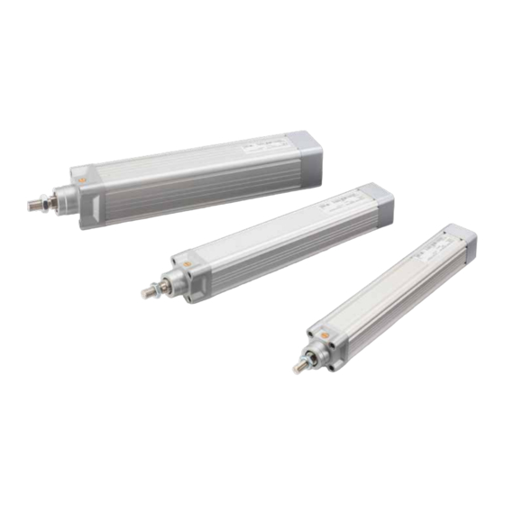
4 .0 S tr u c t u r e a n d f u n c ti o n 4.0 Structure and function 4.1 Brief description 4.2 Direction of motor The CASM (⮑ Fig. 1) is a linear actuator designed to work in during extension of the factory automation. -
Page 10: Overview
C A S M 4.3 Overview 4.4 Sensor mounting • The sensor can be inserted into the grooves by sliding it in 4.3.1 CASM accessories overview from the front. (⮑ Fig. 6). Fig. 3 • Install the sensors: the sensors can be slided into the grooves from the front of the actuator. -
Page 11: Delivery, Packaging And Storage
5 .0 D e l i v e r y, p a c k a g i n g a n d s to r a g e 5.0 Delivery, packaging and storage 5.3 Returning actuator to 5.1 Safety information for the manufacturer transporting Proceed as follows for the return transport:... -
Page 12: Storage
C A S M 5.5 Storage Pack the actuator in its original packaging for storage. • Do not store outside. • Storage should be dry and dust-free. • Keep away from any aggressive media. • Protect from UV radiation. • Avoid mechanical vibrations. • ... -
Page 13: Installation And Initial Operation
6 .0 I n s t a l l a ti o n a n d i n i ti a l o p e r a ti o n 6.0 Installation and initial operation Authorized personnel The CASM Linear actuator (⮑ Fig.6) is attached to two ele- ments via the push tube and the mounting accessories. - Page 14 C A S M NOTE Information concerning the dimensions of the drill holes for fastening bolts can be found in the respective data sheets. (⮑ 11 Appendix, page 28). WARNING Risk of injury and material damage due to insufficient fastening! Only use fastening bolts and secure them adequately.
-
Page 15: Operation
7.0 O p e r a ti o n 7.0 Operation 7.1 Safety NOTICE Actuator may be damaged if liquids enter the actuator during extension and retraction. Keep liquids away. DANGER Risk of crushing While moving onto solid objects, the force of the device may NOTICE cause injuries. -
Page 16: Installation Instruction Casm Inline Kit
In principle, beside the recommended motors, also 3rd party motors may be fitted. It is important that torque and speed specifications of the motor do not exceed the permit- ted values of the linear unit. Detailed information may be found in the technical notes relating to the electrical cylin- ders. Ewellix recommends, amongst others, the following Siemens servo motors (table 1). Table 1 Linear unit CASM–32 CASM–40... -
Page 17: Coupling Installation
7.3.4 Coupling installation Table 4 Positioning dimensions for coupling with foot mounting Step 1 • Separate the two coupling halves (⮑ fig. 8). Fig. 8 Standard Motor X2 Linear unit Y2 CASM-32-1FK7015 20,9 18,1 CASM-32-1FK7022 23,7 18,9 CASM-40-1FK7022 22,5 20,2... -
Page 18: Adapter Kit Installation
C A S M 7.5.5.1 Foot mounting option 7.3.5 Adapter kit installation Fitting the foot mounting First fit the foot mounting (FB) to the linear unit (LE) and then NOTE The relevant seal must always be fitted between all components the coupling housing (K). Insert one square seal with cut-out to ensure the requisite degree of IP protection. (D1) between each of the components, and secure the hous- ing (K) using four Allen screws (S1) to the linear unit (LE). -
Page 19: Installation Instruction Casm Parallel Kit
Detailed information may be found in the technical notes relating to the electric cylinders. Ewellix rec- ommends the following SIEMENS 1FK7 servo motors: (⮑ table 1). -
Page 20: Timing Belt Installation
(P) and the 2nd clamping sleeve on the motor side as follows: • CASM-32: Push the pulley as far as possible • CASM-40/63: Position the pulley by placing the assembly tool (MH) on the intermediate plate and pushing the pulley as far as possible. -
Page 21: Gearbox Cover Installation
Place the flat seal (D3) in between the gearbox cover (D) and screws (torque as per table 5). the intermediate plate (ZW). Push the sealing washers (DS) Table 5 over the Allen screws (S1/S2) and fix the gearbox cover (Fig. 14). For screws and torques, refer to table 2. (CASM-32) (CASM-40) (CASM-63) Screw Torque M Screw... -
Page 22: Maintenance
C A S M 8.0 Maintenance Personnel • Daily maintenance work described herein can be per- formed by the operator. • Some maintenance tasks should only be performed by specially trained, qualified personnel employed by the product owner, or exclusively by personnel of the manu- facturer; specific reference will be made in each case in the description of the respective maintenance task. -
Page 23: Maintenance Work
8 .0 M a l f u n c ti o n s 8.2 Maintenance work 8.2.3 Check of visual condition To be performed by qualified personnel. 8.2.1 Cleaning 1. Separate the device from the energy supply. To be performed by operator. 2. Check the following structural components for visual ex- ternal damage: NOTICE • ... -
Page 24: Maintenance Checks
C A S M 8.4 Maintenance checks During each service interval, the following measurement/ check needs to be done: • LS: the axial play must be less than the following values: CASM–32 CASM–40 CASM–63 0,35 mm 0,6 mm 1,0 mm If the play is above the specified values, the drive needs to ... -
Page 25: Malfunctions
9.0 M a l f u n c ti o n s 9.0 Malfunctions The following chapter describes potential causes for disrup- tions and the work that is necessary to restore operation. Actions during malfunctions In the event of more frequent malfunctions, shorten the 1. -
Page 26: Malfunction Table
C A S M 9.1 Malfunction table Malfunction Possible cause Repair malfunction To be repaired by Linear actuator Obstacle in the stroke area of the linear Remove all obstacles in the stroke area. Operator. doesn’t move actuator. Incorrect load. Measure static and dynamic load and compare Qualified personnel. -
Page 27: Dismantling
1 0.0 D i s m a n tl i n g 10.0 Dismantling 10.1 Disposal Personnel • The dismantling may only be carried out by specifically To the extent that no take-back or disposal agreement has qualified personnel. been put in place, disassembled components should be • Work on the electric system may only be performed by recycled. -
Page 28: Appendix
C A S M 11.0 Appendix Technical data sheets PUB NUM IL-06010/1-EN-May 2020 Electric cylinders CASM 32/40/63 For further technical information please contact Ewellix. - Page 29 © Ewellix All contents of this publication are the property of Ewellix, and may not be re- produced or given to third parties (even extracts) without permission. Although great care has been taken in the production of this catalog, Ewellix does not take any responsibility for damage or other loss resulting from omissions or ty- pographical errors.
Need help?
Do you have a question about the CASM-32 and is the answer not in the manual?
Questions and answers