
Related Manuals for Ewellix CASM-100


Summary of Contents for Ewellix CASM-100
- Page 1 M A X 2 L I N E S I N S TA L L AT I O N , O P E R AT I O N A N D M A I N T E N A N C E M A N UA L CASM-100...
-
Page 3: Table Of Contents
Contents 7.5 Installation instruction CASM-100 ....... 16 1.0 General information ............4 7.5.1 Motor adapter ............16 1.1 Information about this manual ........4 7.5.2 Recommended motors ........... 16 1.2 Explanation of symbols and signal words ......4 7.5.3 Coupling installation ..........16 1.3 Limitation of liability ............4... -
Page 4: General Information
C A S M -1 0 0 1.0 General information 1.1 Information about this DANGER Indicates a dangerous situation, which manual will lead to death or serious personal injury, if the precautionary measures are ignored. This manual provides important information on how to work with the actuator (also called device or drive) safely and efficiently. -
Page 5: Limitation Of Liability
Ewellix reserves the right to seek compensation for viola- tions of these restrictions. 1.5 Spare parts The CASM-100 linear actuator is not meant to be repaired by customer personnel . All warranty and service claims become void without notice if any screws on the linear actuator have... -
Page 6: Safety
C A S M -1 0 0 2.0 Safety prevailing at the site where the device is installed. The risk This chapter provides an overview of all important safety assessment must be implemented in the form of work in- precautions for protection of personnel as well as safe and structions for device operation. -
Page 7: Personnel Requirements
Use only qualified, trained personnel (as described below) who vice unless they have been specifically authorized by have read, understand and follow these instructions. Ewellix. 2.3.1 Qualifications 2.5.1 Warning labels The following qualifications are specified for different areas The symbol to the left can be found on the actuator of activity listed in the manual. -
Page 8: Technical Data
C A S M -1 0 0 3.0 Technical data 3.2 Product labels NOTE The technical data (dimensions, weight, output, connection 3.2.1 Linear unit label values, etc.) can be found in the drawings and data sheets at the end of this manual (⮑ 11 Appendix, page 27). 3.1 Operating conditions Environment Information... -
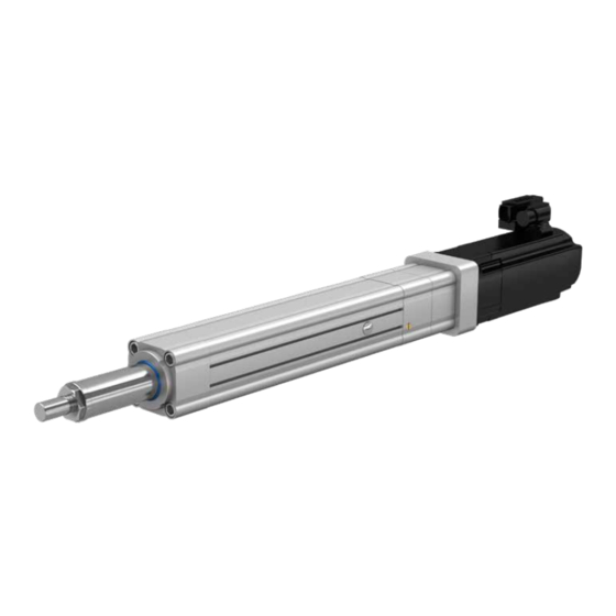
Page 9: Structure And Function
4.0 Structure and function 4.1 Brief description 4.2 Direction of motor The CASM-100 (see image below) is a mechanical drive de- during extension of the signed to work in factory automation. The drive is used ex- clusively for dynamic center compression or traction cylinder movement. -
Page 10: Sensor Mounting
C A S M -1 0 0 4.4 Sensor mounting • Sensor can be inserted in two slots s on the CASM-100 electro cylinder (see image below). • Install the sensors: the sensors can be inserted into the slots from above. The cable ends should lead into the drive direction. -
Page 11: Delivery, Packaging And Storage
5.2 Delivery inspection Only environmentally- friendly materials were used for the packaging. The CASM-100 linear actuator is delivered as one packaged The packaging is supposed to protect the individual compo- unit in a box or on pallets. nents from damage caused by the transport, corrosion and Check the delivery for completeness and damage immedi- other damage until they are ready for installation. -
Page 12: Storage
C A S M -1 0 0 5.5 Storage Pack the actuator in its original packaging for storage. • Do not store outside. • Storage should be dry and dust-free. • Keep away from any aggressive media. • Protect from UV radiation. • ... -
Page 13: Installation And Initial Operation
6 .0 I n s t a l l a ti o n a n d i n i ti a l o p e r a ti o n 6.0 Installation and initial operation Authorized personnel The CASM-100 Linear actuator (see image below) is at- tached to two elements via the push tube and the mounting The installation and initial operation may only be conducted accessories. - Page 14 Warning labels, page 7). 10. Start set-up for reference travel with limited load and speed: CASM-100: 1 x 10⁻³ J maximum NOTICE Do not reach the mechanical limit of the drive during operation. Doing so will result in irreversible damage to the drive.
-
Page 15: Operation
7.0 O p e r a ti o n 7.0 Operation 7.1 Safety NOTICE Material damage through overheating DANGER An overheating of the device can cause damage. Risk of crushing Therefore: While moving onto solid objects, the force of the device may • ... -
Page 16: Installation Instruction Casm-100
CASM-100 7.5.1 Motor adapter The motor adapter is to install a motor with an axially de- signed shaft (⮑ 7.5.2 Recommended motors) to a CASM-100 linear unit. 7.5.2 Recommended motors The Siemens motors provided by SKF come with a differen- tial resolver or multi-turn encoder, a shaft-end with keyway (1FK7044 without) and a holding brake. In addition, they are equipped with a Drive-CLiQ interface. -
Page 17: Synchronous Servo Motors
7.0 O p e r a ti o n NOTE For the following steps, check the required screw size and the tightening torques using the values indicated in table 1 and 2. 7.5.4 Synchronous Servo Motors Inline mounting • Attach the coupling (C1) on the linear unit (LU) using screw (S4) as described in 7.5.3. - Page 18 C A S M -1 0 0 Parallel mounting • Fit the linear unit (LU) onto the gearbox (GB) by inserting the gasket (G3) between the two components and tighten the screws (S1). • Attach the coupling (C1) to the motor (M) using screw (S4) as described in 7.5.3.
-
Page 19: Asynchronous Motors
7.0 O p e r a ti o n 7.5.5 Asynchronous Motors Inline mounting SM3* *These screws depend on the motor type they do not correspond to the same indices as in table 1 • Attach the coupling (C1) to the motor (M) using screw (S4). • ... - Page 20 C A S M -1 0 0 Parallel mounting • Attach the coupling (C1) to the motor (M) using screw (S4) as described in 7.5.3. • Put the sealing (G1) into the groove in the motor flange (MF) and tighten the flange with four screws (SM3). • Fit the linear unit (LU) onto the gearbox (GB) by inserting the gasket (G3) between the two components and tighten the screws (S1).
-
Page 21: Maintenance
If increased wear is detected during regular inspections, shorten the required maintenance intervals according to the actual indications of wear. CASM-100 linear actuator maintenance plan Interval Maintenance work To be carried out by Check actuator for visible damage (⮑ 8.2.3 Check of visual condition, page 22). -
Page 22: Maintenance Work
8.2.4 Relubrication interval To be performed by qualified personnel. The relubrication device is optional. Check if the CASM-100 is equipped with a relubrication plug on the protection tube (1). 1. Run the the actuator to the relubrication position (⮑ table 3) 2. -
Page 23: Measures After Maintenance Completed
8 .0 M a i n te n a n c e WARNING Risk of injury and material damage! Only open the relubrication bore when the actuator is stopped and powered off. Table 3 CASM-100 linear actuator relubrication interval Type Relubrication position Relubrication interval Amount of lubricant Screw type... -
Page 24: Malfunctions
Risk of injury and material damage due to incorrect repair of malfunction The CASM-100 linear actuator is not designed to be repaired by the customer in most situations . Incorrect repair of a malfunction may lead to personal injury or material damage. -
Page 25: Malfunction Table
Qualified personnel. nominal load and install stronger actuator if necessary. Lifespan of the device is exceeded. See performance diagram in the CASM-100 Qualified personnel. brochure. Linear actuator cannot be set in motion Exchange device. Qualified personnel. -
Page 26: Dismantling
• Contact the manufacturer if you have any questions or concerns. 10.1 Dismantling of CASM-100 1. Secure elements of the application in such a fashion that no loads can impact the fork and the hinge head. -
Page 27: Appendix
Technical data PUB NUM IL-07016-EN-October 2019 Electric cylinder CASM–100 For further technical information please contact Ewellix. For quick reference, the most relevant performane parame- ters are shown in the following section. 11.1 Ingress Protection The following position in the type key defines the rated in-... -
Page 28: Load
C A S M -1 0 0 11.2 Load Load CASM-100-XX-####-##Y##Z#-… Max. dynamic axial force Max. dynamic axial force L10 Max. static axial force 23kN 22kN 52kN 48kN 47kN 60kN 60kN 60kN 60kN 85kN 50kN 82kN Unless the following limits are more restricting: Load See fig. “Pivot Mount Lifetime Chart”... -
Page 29: Linear Speed
11 .0 A p p e n d i x 11.3 Linear Speed CASM-100-XX-####-#######-Z#####-… Max. linear speed 260 mm/s 210 mm/s 750 mm/s 890 mm/s C or D 100 mm/s 11.4 Gearbox Output Torque If a gearbox is selected, the following maximum output tor- ques must be respected: CASM-100-##-####-#######-######-GX-YY#-##-…... - Page 30 © Ewellix All contents of this publication are the property of Ewellix, and may not be re- produced or given to third parties (even extracts) without permission. Although great care has been taken in the production of this catalog, Ewellix does not take any responsibility for damage or other loss resulting from omissions or ty- pographical errors.
Need help?
Do you have a question about the CASM-100 and is the answer not in the manual?
Questions and answers