
Related Manuals for Ewellix CAHB-2E Series


Summary of Contents for Ewellix CAHB-2E Series
- Page 1 CAT E G O R Y M A X 2 L I N E S I N S TA L L AT I O N , O P E R AT I O N A N D M A I N T E N A N C E M A N UA L CAHB-2xE series Linear actuator CAHB-20E, CAHB-21E and CAHB-22E...
-
Page 3: Table Of Contents
Contents General information ...........4 6.3 Inspections prior to first operation......19 Information on this manual ..........4 Connect to power supply ........... 19 Explanation of symbols and signal words ....4 6.4.1 Wiring scheme: ............19 Limitation of liability .............5 6.4.2 Define moving direction VS power “+”,”-” ..... 19 Warranty terms .............5 Operation ..............20 Customer service ............5 Safety ................20... -
Page 4: General Information
C A H B -2 0 s e r i e s General information Information on this DANGER Indicates a dangerous situation, which manual will lead to death or serious personal injury, if the precautionary measures are ignored. This manual provides important information on how to work with the actuator safely and efficiently. WARNING The manual is part of the actuator, must always be kept in Indicates a dangerous situation, which the actuator’s direct proximity and should be available for... -
Page 5: Limitation Of Liability
1.4 Warranty terms The applicable and effective warranty terms are those con- tained in the manufacturer’s terms and conditions of sale. 1.5 Customer service Ewellix Customer Service is always available to provide tech- nical information and answer questions. The contact information for Ewellix Customer Service can be found on www.ewellix.com. -
Page 6: Safety
C A H B -2 0 s e r i e s 2.0 Safety 2.1 Limitation of liability In addition to the safety instructions in this Manual, the owner or processor must do the following concerning these This chapter provides an overview of important safety pre- safety and acci-dent prevention guidelines and environmen- cautions and information necessary for safe and trou- tal precautions regulations applicable to the site of the sys- ble-free installation, operation and maintenance. -
Page 7: Qualifications
2 .0 S afe t y 2.2.1 Qualifications WARNING Danger of injury caused by moving components! The following qualifications are specified for different areas Rotating and/or linearly moving components can cause severe injury. of activity listed in the Manual. Therefore: • An instructed person (Operator) • Do not work on or place any of your body, hands, or arms near has been instructed by the customer in an orientation ses- moving components. -
Page 8: Changes And Modifications On The Actuator
CAUTION Continued operation of the clutch can result in overheating and damage to the linear actuator. If clutch activates, switch off power immediately. 2.4 Changes and modifications on the actuator To avoid hazardous situations and to ensure optimal perfor- mance, do not make any changes or modifications to the ac- tuator unless they have been specifically authorized by Ewellix. -
Page 9: Technical Data
• Full performance: 0 ~ 40 °C • Encoder option: 4–20 V DC • Degraded performance: below 0 °C, above 40 °C. (The load ca- • Potentiometer option: Voltage limited by power 2 W pacity and speed would degraded, the current would rise, can • For absolute analog position sensor: 10~55 V DC (current contact Ewellix for more information). consumption 15 mA max.) 24 V DC & 48 V DC version – Duration (intermittent) 48 V DC version: supply voltage Information Value Unit • For actuator: 40 ~ 55 V DC... -
Page 10: Product Label
XX VDC, XX A, XXX N (pull/push), XXX mm/s Duty cycle XX% (85s on / XXXs off) Serial No. YYYYMMDDXXXX IP66M / IP69K Ewellix Motion Technologies (Pinghu) Co., Ltd. The product label provides the following information 1. Identification of actuator (type key) 2. Part number 3. Customer part number 4. -
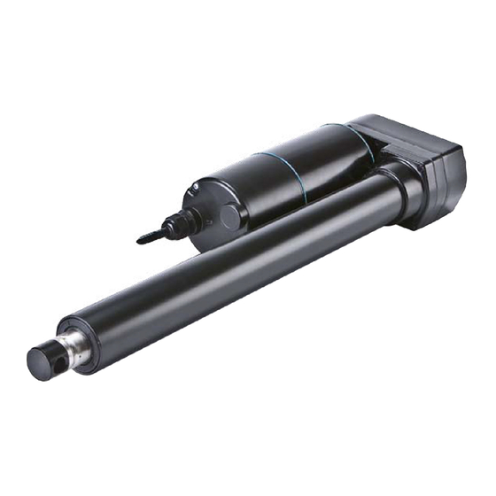
Page 11: Structure And Function
4 .0 S tr u c t u r e a n d f u n c ti o n 4.0 Structure and function 4.1 Overview CAHB- 20 E Include 3 types outline. Fig. 2 CAHB-20 E without feedback 1. Front hinge head 2. - Page 12 C A H B -2 0 s e r i e s CAHB-21 E and 22 E Include 3 types outline. Fig. 5 CAHB-21 E and 22 E without feedback 1. Front hinge head 2. Push tube 3. Guiding tube (Al alloy tube) 4.
-
Page 13: Brief Description
4 .0 S tr u c t u r e a n d f u n c ti o n 4.2 Brief description 4.3 Special features Mechanical overload protection Overview The actuator contains a mechanical overload protection unit Fig. 8 (clutch).This overload protection unit will activate if the linear unit of the actuator overloads. -
Page 14: Construction Group Description
1. Wires to connect actuator to power supply or to an exter- nal control. 4.6 Options If not specified otherwise, the options listed below are avail- able for the entire series of CAHB-2… linear actuators. 4.6.1 Limit switch The limit switch makes it possible to control the stroke of the linear unit by internal setting. Contact the Ewellix to adjust the setting of limit switch. Remark: Limit switch is not available for CAHB-20... -
Page 15: Absolute Analog Position Output
4 .0 S tr u c t u r e a n d f u n c ti o n 4.6.3 Absolute analog position output 4.6.4 Encoder The absolute analog position sensor is a multitude non-con- Dual hall sensor for incremental position feedback. It outputs tact magnetic sensor. It provides a signal indicating the posi- signals when the actuator is moving outwards and inwards tion of the linear actuator. the output signal is 0 ~ 5V DC volt- respectively. The output signals, channel 1 and 2, are ±90°,... -
Page 16: Transport, Packaging And Storage
C A H B -2 0 s e r i e s 5.0 Transport, packaging and storage 5.1 Safety information for 3. Send to manufacturer. the transport 5.1.3 Packaging For packaging CAUTION The individual packaged pieces have been packaged appro- Significant actuator damage can occur if not properly transported, unpacked and stored. -
Page 17: Installation And First Operation
6 .0 I n s t a l l a ti o n a n d f i r s t o p e r a ti o n 6.0 Installation and first operation 6.2 Installation Authorized personnel • The installation and first start of operation may only be conducted by qualified personnel. -
Page 18: Inspections Prior To First Operation
C A H B -2 0 s e r i e s 2. Ensure that the applied force on the fastening bolts is al- ways centrically directed on the actuator (⮑ Fig. 13). Fig. 13 Correct installation Issues schemes: Parallell issue Misaligned issue WARNING 6.3 Inspections prior to Risk of injury and material damage due to incorrect... -
Page 19: Connect To Power Supply
6 .0 I n s t a l l a ti o n a n d f i r s t o p e r a ti o n 6.4 Connect to power 6.4.2 Define moving direction VS power supply “+”,”-”... -
Page 20: Operation
C A H B -2 0 s e r i e s Operation Safety 7.2 Action before operation DANGER Risk of crushing! Ensure that there are no persons or objects in the stroke Actuator may cause serious injuries while moving. Therefore: area of the actuator. -
Page 21: Disengagement In Case Of Emergency
7.0 O p e r a ti o n DANGER Electrical shock hazard Incorrect installation can result in serious injuries, death or damage. Only professional electricians should work on electrical systems. 7.4 Disengagement in case of emergency In hazardous situations, all movements of the actuator must be stopped as quickly as possible and the power supply must be turned off. Proceed as follows in hazardous situations: 1. -
Page 22: Maintenance
Therefore: • Use only genuine spare parts from the manufacturer. • Spare parts in/on the actuator may only be replaced by Ewellix. The actuator must be dismantled and sent to the manufac- turer. The address is listed on the cover back. -
Page 23: Maintenance Work
3. Check stainless steel tube for scratches and inden- • The inspections and readings must be performed as re- tations 3. Notify processor or Ewellix in case of damage quired by the applicable standards and regulations. The list 4. If there is no damage and the processors/manufacturer of the applicable standards can be found in the appendix. -
Page 24: Malfunctions
C A H B -2 0 s e r i e s 9.0 Malfunctions The following chapter describes potential causes for mal- Behavior during malfunctions functions and the work that is necessary to restore In principle: operation. 1. In the event of a malfunction that may present an imme- In the event of frequent malfunctions, shorten the mainte- diate danger to persons or assets, turn off the actuator or nance intervals. -
Page 25: Malfunction Table
Send actuator for repair Insufficient power supply Increase power supply Voltage drop in cable Thicker cable Apply under lower temperature Contact Ewellix for suitable (performance would degrade actuator type below 0 °C) Obstacle in the stroke area of the Remove all obstacles in the stroke... -
Page 26: Dismantling
C A H B -2 0 s e r i e s 10.0 Dismantling 10.1 Dismantling Personnel • The dismantling may only be carried out by specifically 10.1.1 Dismantling of CAHB-20 series qualified personnel. 1. Separate actuator from energy supply (⮑ 7.4 Disen- • Work on the electric system may only be performed by gagement in case of emergency, page 21). -
Page 27: Appendix
11 .0 A p p e n d i x 11.0 Appendix Technical data sheets Please refer to the following document: Actuator range catalogue PUN BUM IL-05002/1-April 2020... - Page 28 © Ewellix All contents of this publication are the property of Ewellix, and may not be re- produced or given to third parties (even extracts) without permission. Although great care has been taken in the production of this catalog, Ewellix does not take any responsibility for damage or other loss resulting from omissions or ty- pographical errors.
Need help?
Do you have a question about the CAHB-2E Series and is the answer not in the manual?
Questions and answers