
Related Manuals for Ewellix CAHB-10


Summary of Contents for Ewellix CAHB-10
- Page 1 M A X 2 L I N E S I N S TA L L AT I O N , O P E R AT I O N A N D M A I N T E N A N C E M A N UA L CAHB-10...
-
Page 3: Table Of Contents
Brief description ............10 10.0 Dismantling ...............24 4.3 Construction group description ......... 11 10.1 Dismantling ..............24 Connections .............. 11 10.1.1 Dismantling of CAHB-10 ........24 Features ..............12 10.2 Disposal ..............24 4.5.1 Limit switch ............12 11.0 Appendix ..............25 4.5.2 Potentiometer ............12 4.5.3 Thermal switch ............ -
Page 4: General Information
C A H B -1 0 s e r i e s General information Information on this DANGER Indicates a dangerous situation, which manual will lead to death or serious personal injury, if the precautionary measures are ignored. This manual provides important information on how to work with the actuators afely and efficiently. WARNING The manual is part of the actuator, must always be kept in Indicates a dangerous situation, which the actuator’s direct proximity and should be available for... -
Page 5: Limitation Of Liability
1.4 Warranty terms The applicable and effective warranty terms are those con- tained in the manufacturer’s terms and conditions of sale. 1.5 Customer service Ewellix Customer Service is always available to provide tech- nical information and answer questions. The contact information for Ewellix Customer Service can be found on www.ewellix.com. -
Page 6: Safety
C A H B -1 0 s e r i e s 2.0 Safety This chapter provides an overview of important safety pre- tal protection regulations applicable to the site of the sys- cautions and information necessary for safe and trou- tem’s installation: ble-free installation, operation and maintenance. • Inform themselves of applicable industrial safety precau- Disregarding this Manual and safety precautions specified tions and determine additional hazards that arise due to therein may result in considerable danger and possible seri-... -
Page 7: Qualifications
2 .0 S afe t y 2.3.1 Qualifications WARNING Danger of injury caused by moving components! The following qualifications are specified for different areas Rotating and/or linearly moving components can cause serious of activity listed in the manual. injury. Therefore, follow the precautions below: • An instructed person (Operator), has been instructed by the owner in an orientation session • Do not work on or place any of your body, hands, or arms near on the assigned tasks and possible dangers in case of im- moving components. -
Page 8: Changes And Modifications On The Actuator
The following safety features may have been installed: In its standard version, the actuator features a thermal switch protection integrated into the motor housing. This switch protects the motor from overheating. CAUTION To prevent damage from overheating, do not try to operate actuator until its temperature has fallen below the threshold for the switch to operate (95 °C) . 2.6 Changes and modifications on the actuator WARNING To avoid hazardous situations and to ensure optimal performance, do not make any changes or modifications to the actuator unless they have been specifically authorized by Ewellix. -
Page 9: Technical Data
3 .0 Te c h n i c a l d a t a 3.0 Technical data NOTE The technical data (dimensions, weight, output, connection values etc.) can be found in the enclosed drawings and data sheets (⮑ 11 Appendix, page 25). 3.1 Operating conditions Environment Information Value Unit Temperature range –40 to +85 °C Relative atmospheric humidity up to 95 (no build up of condensation) Duration (intermittent) -
Page 10: Structure And Function
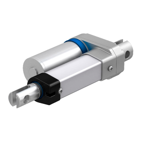
C A H B -1 0 s e r i e s 4.0 Structure and function 4.1 Overview CAHB- 10 Fig. 2 CAHB-10 1. Cable 2. Motor part 3. Gearbox 4. Front hinge head 5. Push tube 6. Guide tube 7. Rear hinge head 4.2 Brief description... -
Page 11: Construction Group Description
The linear unit is connected to the motor with several screws. These screws should not be loosened or removed. 4.4 Connections Fig. 4 CAHB-10 connections 1. Wires to connect actuator to power supply or to an external control. -
Page 12: Features
C A H B -1 0 s e r i e s 4.5 Features 4.5.4 2-Hall encoder (optional) The 2-Hall encoder provides a signal indicating the position If not specified otherwise, the options listed below are avail- of the linear actuator. able for the entire series of CAHB-10 linear actuators It is equipped with 2 Hall effect sensors 45° electrically 4.5.1 Limit switch shifted. The limit switch makes it possible to control the stroke of the linear unit by internal setting. -
Page 13: Transport, Packaging And Storage
24). 2. Pack the actuator in its original packaging. Follow stor- • Proceed carefully during the unloading of the packaged items and 5.5 Storage, page 14). age conditions ( ⮑ during the delivery as well as during transport to its final destina- 3. Send to manufacturer. Contact Ewellix service to obtain tion. Comply with the symbols and information shown on the a shipment address. packaging. • Only remove the actuator from its packaging right before installa- 5.4 Packaging tion. -
Page 14: Storage
C A H B -1 0 s e r i e s 5.5 Storage Pack the actuator in its original packaging for storage. • Do not store outside. • Dry and dust-free storage. • Keep away from any aggressive media. • Protect from UV radiation. • Avoid mechanical vibrations. • Storage temperature: -55 to 90 °C. • Relative atmospheric humidity: max. 95% (no build up of condensation). -
Page 15: Installation And First Operation
6 .0 I n s t a l l a ti o n a n d f i r s t o p e r a ti o n 6.0 Installation and first operation 6.2 Installation Authorized personnel • The installation and first start of operation may only be conducted by qualified personnel. The CAHB-10 linear actuator can be attached over two ele- • Work on the electric system may only be performed by ments, via the front rod end (1) and the trunnion mount (2) professional electricians. (the trunnion has two options: pins and bushings). WARNING 1. -
Page 16: Inspections Prior To First Operation
C A H B -1 0 s e r i e s WARNING Risk of injury and material damage due to incorrect installation! During installation, do not subject the actuator to side-impact or to turning forces. 3. During installation, make sure that the linear actuator is not blocked in its movement over the entire stroke. 4. During installation, be sure that the motor cable is not squeezed, clamped or pulled. 5. Connect linear actuator to power supply (⮑ 6.4 Con- nect to power supply, page 16). -
Page 17: Operation
• Never tamper with the elements that are connected to the actua- 7.3.1 Normal operation tor while the actuator is in operation. During normal operation, the linear actuator lifts and lowers the elements that are connected with the CAHB-10 linear ac- CAUTION tuator via the hinge head. Risk of injury through contact with the hinge head! -
Page 18: Disengagement In Case Of Emergency
C A H B -1 0 s e r i e s 7.4 Disengagement in case of emergency In hazardous situations, all movements of the actuator must be stopped as quickly as possible and the power supply must be turned off. Proceed as follows in hazardous situations: 1. Immediately engage emergency shut-off, if present, or cut off power for actuator. 2. Evacuate people from the hazard zone and initiate first aid measures. -
Page 19: Maintenance
If the linear actuator is used outside of the environmental conditions Wrong or faulty spare parts can adversely affect safety and cause specified earlier in this manual, check such components once a damage, malfunctions or total failure. month for any changes such as oxidation or sedimentation. Therefore, follow the precautions below: • Spare parts in/on the actuator may only be replaced by Ewellix. The actuator must be dismounted and sent to the manufac- turer to replace any spare parts. -
Page 20: Cleaning
Damage due to incorrect cleaning! Therefore, follow the precautions below: • Do not use any aggressive cleaning agents. Water used for clean- ing including chemical additives must be pH-neutral. • Liquids must not touch the actuator during the retraction or ex- tension. • Only use additional cleaning materials listed by the Ewellix. • No steam jets or pressure washers may be used to clean. • Other cleaning agents or cleaning devices may only be utilized with the manufacturer’s approval. Clean line actuator: 1. Separate the actuator from the energy supply. 2. Clean dirty parts with a damp cloth. -
Page 21: Check Of Visual Condition
Fig. 9 1. Check connecting cables for cracks, cuts and pinched sections 2. Check hinge hole for cracks, deformation and broken pieces 3. Check stainless steel tube for scratches and in- dentations 3. Notify processor or Ewellix in case of damage 4. If there is no damage and the processors/manufacturer has not communicated any concerns, reconnect the ac- tuator to the power supply. 8.4 Measures after completed maintenance Upon completion of the maintenance, the following steps have to be performed prior to restarting the device. 1. Ensure that all tools, material and other equipment used during maintenance have been removed from the work area. -
Page 22: Malfunctions
Risk of injury and device damage due to incorrect repair of malfunction Therefore, follow the precautions below: • Never loosen the screws on the device or try to open it. • In the event of a malfunction that cannot be fixed by following the steps in the malfunction table in this operating manual, dismantle the actuator and send it to Ewellix for repair (⮑ 5.0 Transport, packaging and storage, page 13). -
Page 23: Malfunction Table
9.0 M a l f u n c ti o n s 9.1 Malfunction table Malfunction Possible cause To repair malfunction To be repaired by Linear actuator doesn't move No supply voltage Check power supply Professional electrician Plug contacts: Lack of plug contact or plug has Device control unit, Operator not been inserted properly control of voltage network. -
Page 24: Dismantling
• Secure structural components in a way so they would not be able Damage can be caused to the environment due to incorrect to fall or tip over. disposal! • Contact Ewellix if you have any questions or concerns. Electronic waste, electronic components, lubricants and other additives are subject to special waste treatment regulations and may only be disposed of by approved specialized companies! -
Page 25: Appendix
11 .0 A p p e n d i x 11.0 Appendix Technical data sheets The following pages are a reprint from IL-05002-EN-actuator-range-catalogue... - Page 26 C A H B -1 0 s e r i e s CAHB-10 Linear actuator Benefits • Compact design • Designed for harsh environment • Robust and reliable • Integrated limit switches • Quiet operation • Thermal protection • Optional potentiometer and 2-Hall encoder available • Electromagnetic compatibility (EMC) compliant Technical data Designation Unit CAHB–10... 1 CAHB–10...
- Page 27 Performance diagrams Speed-load diagram Current-load diagram Speed [mm/s] Current consumption [A] 12 V DC 24 V DC 1 000 1 200 1 400 1600 1 000 1 200 1 400 1600 Load [N] Load [N] CAHB-10...1 CAHB-10...3 CAHB-10...5 CAHB-10...6 CAHB-10...2 CAHB-10...4...
- Page 28 C A H B -1 0 s e r i e s Dimensional drawing Optional potentiometer Stroke S + 34 ØB ØA 36,5 Ø20 Ø20 20,5 Ø38 12,5 Legend: and L = retracted length Cable length L ±30 Stroke S + 34 Ø20 +0,5...
- Page 29 11 .0 A p p e n d i x Encoder resolution Type CAHB-10...1 CAHB-10...2 CAHB-10...3 v CAHB-10...4 CAHB-10...5/6 mm/pulse 0,15 0,075 0,05 0,0375 Potentiometer resolution Stroke [mm] 50~80 80~160 160~300 Minimum resistence value of potentiometer 700~1 300 Ω 700~1 300 Ω 700~1 300 Ω Potentiometer resolution 100 Ω/mm 50 Ω/mm 16,6 Ω/mm Absolute analog output...
- Page 30 C A H B -1 0 s e r i e s Connecting diagram Connecting diagram Basic configuration 2-Hall encoder Basic configuration 2-Hall encoder 12/24 V DC 12/24 V DC 12\24 V DC 12\24 V DC – – + 5V Black Yellow Hall A...
- Page 31 11 .0 A p p e n d i x Ordering key C A H B – 1 0 – – – A – 0 0 0 Type Voltage 12 V DC 24 V DC Load 120 N 240 N 500 N 750 N 1 000 N 1 500 N Screw TR12 screw Customized Stroke 50 mm...
- Page 32 © Ewellix All contents of this publication are the property of Ewellix, and may not be re- produced or given to third parties (even extracts) without permission. Although great care has been taken in the production of this catalog, Ewellix does not take any responsibility for damage or other loss resulting from omissions or ty- pographical errors.
Need help?
Do you have a question about the CAHB-10 and is the answer not in the manual?
Questions and answers