BVL V-MIX DRIVE Maximus Plus 11-1S Operating Manual
Self-propelled mixer wagon
Hide thumbs
Also See for V-MIX DRIVE Maximus Plus 11-1S:
- Operating manual (214 pages) ,
- Operating manual (205 pages) ,
- Operating manual (90 pages)
Table of Contents
Advertisement
Quick Links
English
V-
MIX DRIVE
Maximus Plus 11-1S/13N-1S/13H-1S/15-1S/17-1S
Rev. 0/04.20
Printed in Germany – translation of the original Operating manual
Read and follow this operating manual before putting the machine into operation for the first time!
Store for future reference!
Type of manual
ing manual
Machine designation
Drive
MachineNo
MachineType
chine
Revision status
CustomerName
van Lengerich
CustomerNameAffix
chinenfabrik GmbH & Co. KG
CustomerAddress
Operating manual
16
CustomerLocation
48488 Emsbüren
CustomerPhone
(0)5903 951-0
CustomerFax
(0)5903 951-34
CustomerEmail
fo@bvl-group.de
CustomerURL
bvl-group.de
DocuStatus
CustomerPOBox
1154
Year of Manufacture
Item no. 117924
Operat-
V-MIX
114628
Ma-
1
Bernard
Mas-
Grenzstraße
D-
+49
+49
in-
http://www.
09.19
Postfach
2019
www.bvl-group.de
Advertisement
Table of Contents

Related Manuals for BVL V-MIX DRIVE Maximus Plus 11-1S


Summary of Contents for BVL V-MIX DRIVE Maximus Plus 11-1S
- Page 1 CustomerNameAffix Mas- chinenfabrik GmbH & Co. KG CustomerAddress Operating manual Grenzstraße CustomerLocation 48488 Emsbüren CustomerPhone (0)5903 951-0 CustomerFax (0)5903 951-34 CustomerEmail fo@bvl-group.de CustomerURL http://www. bvl-group.de DocuStatus 09.19 CustomerPOBox Postfach 1154 Year of Manufacture 2019 MIX DRIVE Maximus Plus 11-1S/13N-1S/13H-1S/15-1S/17-1S Rev. 0/04.20 Item no.
- Page 2 Declaration of Conformity EC Declaration of Conformity according to EC Machinery Directive 2006/42/EC, Annex II A The manufacturer: Bernard van Lengerich Maschinenfabrik GmbH & Co. KG Grenzstraße 16 D-48488 Emsbüren hereby declares the machine named below: Make: Self-Propelled Mixer Wagon Type: Maximus Plus 11-1S/13N-1S/13H-1S/15-1S/17-1S is in conformity with the provisions of the following EC directives:...
- Page 3 Post address: Postfach 1154 D-48488 Emsbüren Tel: +49 (0)5903 951-0 Fax: +49 (0)5903 951-34 Internet: http://www.bvl-group.de Email: info@bvl-group.de Spare part orders / Service For the address, see the manufacturer's address Tel.: +49 (0) 5903 951-566 Fax: +49 (0) 5903 951-37 Emergency no.:...
- Page 4 Note: Register your machine on the BvL service portal or using the record of transfer included with the ma- chine. Your service partner will not be able to file a warranty claim or application for machines that have not been registered.
-
Page 5: Table Of Contents
Contents Contents User information ......................11 Purpose of the operating manual ..............11 Storing the operating manual ................. 11 Locational information in the operating manual ..........11 Illustrations used ..................12 Terms used ....................12 Safety instructions ......................13 Working in a safety-conscious manner ............. 13 Organizational measures ................ - Page 6 Contents 5.1.1.2 Opening the cab door ..................52 5.1.1.3 Closing the cab door ..................53 5.1.1.4 Opening the door window ................54 5.1.2 Driver's seat ....................55 5.1.2.1 Mechanically cushioned driver's seat ..............56 5.1.2.2 Air-suspended driver's seat (special equipment) ..........58 5.1.3 Steering wheel ....................
- Page 7 Contents 5.1.13.4.1.1.2 Inputs of traction drive .................. 94 5.1.13.4.1.1.3 Outputs of traction drive ................95 5.1.13.4.1.1.4 Machine control ..................... 96 5.1.13.4.1.1.5 Status of hydraulic oil filters ................97 5.1.13.4.1.2 Settings ....................... 98 5.1.13.4.1.2.1 Time ......................99 5.1.13.4.1.2.2 Automatic extraction unit ................100 5.1.13.4.1.2.3 Automatic fan reversal unit ................
- Page 8 Contents 5.5.2 Setting the loading arm to the transport position ..........137 Profiled roller and elevator ................138 5.6.1 Switching profiled roller and elevator on and off ..........138 5.6.2 Adjusting the drive speed of the profiled roller ..........139 5.6.3 Adjusting the belt speed of the elevator ............
- Page 9 Contents 9.4.1 Refueling ....................182 9.4.2 AdBlue ....................... 183 9.4.2.1 AdBlue fill level ................... 183 9.4.2.2 Topping off AdBlue ..................184 9.4.3 Working in the engine compartment .............. 185 9.4.3.1 Opening the engine compartment cover ............186 9.4.3.2 Closing the engine compartment cover ............187 9.4.3.3 Opening the assembly hatch .................
- Page 10 Contents 9.15.4 Installing and removing hydraulic hose lines ........... 224 9.16 Tightening torques for bolt joints ..............225 Faults ..........................226 Original Operating Manual V-MIX Drive...
-
Page 11: User Information
User information User information The chapter User information provides you with information on how to use this operating manual. Purpose of the operating manual This operating manual: describes how to operate, clean, service and repair the machine, provides important information on how to handle the machine in a safe and efficient way. If you have any questions, please do not hesitate to contact us. -
Page 12: Illustrations Used
User information Illustrations used Instructions for actions and responses Actions that need to be carried out following a specific sequence are identified as numbered instructions for action. Strictly adhere to this order. In certain cases, the result of the instruction for action will be marked with an arrow. -
Page 13: Safety Instructions
Safety instructions Safety instructions This chapter contains important information for the owner and the operator on how to operate the ma- chine in a safe and trouble-free manner. Observe all safety instructions provided in this operating manual! Most accidents are caused due to a failure to observe the simplest of safety rules. You help prevent accidents by observing all safety instructions provided in this operating manual. -
Page 14: Organizational Measures
Safety instructions Organizational measures The operating manual: must always be stored at the location of the machine, must be freely accessible to operator and maintenance personnel at all times. 2.2.1 Responsibilities of the owner The owner is required to: ... -
Page 15: Qualification Of The Personnel
Safety instructions 2.2.3 Qualification of the personnel Work with/on the machine is limited to qualified and trained personnel. The operator must clearly define the responsibilities of the personnel with regard to operation, maintenance and repairs. A person in training may only work with/on the machine when supervised by an experi- enced member of the personnel. -
Page 16: Product Safety
Safety instructions Product safety 2.3.1 Safe operation of the machine The machine may only be operated by a single person from the driver’s seat on the machine, provided there is no one in the work areas of the machine. See chapter 4.4 “Danger area and hazard areas”, start- ing on page 45. -
Page 17: Warranty And Liability
Safety instructions Wear parts are not covered by warranty! Parts considered wear parts include: Blades including their holders and fasteners Mixing augers, both entire units and parts thereof Shear bolts Conveyor belts Tyres Bearings ... -
Page 18: General Information On Safety And Accident Prevention
Safety instructions apply in general and are intended to ensure the safe operation of the machine, are summarized in the subchapters below. 2.4.1 General information on safety and accident prevention In addition to the safety information provided in this chapter, the general information on safety and accident prevention applicable in the respective country must be observed. - Page 19 Safety instructions Use of the machine Before starting to work, familiarize yourself with all devices and controls of the machine and the way they operate! It will be too late to do so when work is underway. Wear close-fitting clothing! Loose-fitting clothing increases the risk of entrapment or entanglement on shaft drives.
-
Page 20: Hydraulic System
Safety instructions 2.4.2 Hydraulic system The hydraulic system is highly pressurized. Do not block any actuators on the machine which are used to perform direct hydraulic or electrical movements of components, e.g. tipping, swinging and sliding! The respective movement must stop automatically once you release the corresponding actuator. This does not apply to the movements of devices: that are continuous, that are controlled automatically,... -
Page 21: Electrical System
Safety instructions 2.4.3 Electrical system Before performing any work on the electrical system, disconnect the negative terminal of the battery. Use only the designated fuses. Using higher amperage fuses may destroy the electrical system – as there is a risk of fire. ... -
Page 22: Tyres
Safety instructions 2.4.5 Tyres Only trained specialists using the appropriate mounting tools are allowed to perform repairs on tyres and wheels. Before performing any work on the tyres, shut down the machine safely and secure the machine against being lowered and rolling away inadvertently (parking brake, chocks). ... -
Page 23: Mixer Wagon
Safety instructions 2.4.6 Mixer wagon Only one person is allowed to operate the mixer wagon. Keep third parties away from the danger area of the machine before you start operating the machine. It is prohibited: for anyone to stay in the area above the mixer wagon, e.g. for loading the mixing hopper man- ually from a silo or hayloft! Anyone staying in the area above the mixer wagon is at risk of fall- ing into the mixing hopper, to climb onto the upper edge of the mixing hopper,... -
Page 24: Cleaning, Maintenance And Repairs
Safety instructions 2.4.7 Cleaning, maintenance and repairs Adhere to the prescribed intervals for cleaning, servicing and repairs (see maintenance booklet). Secure the machine from being started and rolling inadvertently before cleaning, servicing or repair- ing the machine. Any residual mechanical, hydraulic, pneumatic and electrical or electronic energy stored in the equipment may cause the machine to start moving inadvertently. -
Page 25: Action-Related Safety Instructions And Important Information
Safety instructions Action-related safety instructions and important information The operating manual contains action-related safety instructions and important information. Signal words and symbols are used to allow the reader to view action-related safety instructions and important infor- mation at a glance. 2.5.1 Action-related safety instructions Action-related safety instructions:... -
Page 26: Important Information
Safety instructions 2.5.2 Important information Important information: provides instructions on how to handle the machine properly, provides tips on how to use the machine in the most efficient way possible, is marked by the adjacent symbols. IMPORTANT indicates an obligation to behave or act in a particular way in order to handle the machine in the proper manner. -
Page 27: Warnings
Safety instructions 2.6.1 Warnings A warning is composed of 2 pictograms: (1) Pictogram used to describe the hazard The pictogram is composed of an image illustrating the hazard and enclosed by a triangular safety symbol. (2) Pictogram intended to help avoid the hazard The pictogram is composed of an image providing information on how to avoid the hazard. - Page 28 Safety instructions Order number and explanation 72720 Warning Read and follow the operating manual and the safety instruc- tions before putting the machine into operation! 72723 Warning Risk of personal injury from electric shock or burns caused by coming into contact inadvertently with electric power lines or by approaching high-voltage power lines without authoriza- tion! These hazards may cause serious injury, including death.
- Page 29 Safety instructions 72732 Warning Risk of hands and fingers becoming cut or severed from the movements of parts that are accessible and moving while work is in progress! This hazard may cause serious injury, including the loss of body parts. ...
- Page 30 Safety instructions 72740 Warning Risks from interventions on the machine, such as work for installation, setup, troubleshooting, cleaning, maintenance and repairs, if the machine starts up and rolls away inadvertently! These hazards may cause serious injury, including death. Secure the machine against starting up and rolling away inad- vertently prior to all interventions on the machine.
- Page 31 Safety instructions 72747 Warning Electrical hazards from interventions on the machine! These hazards may cause serious injury, including death. Secure the machine against starting up and rolling away inad- vertently prior to all interventions on the machine. Read and follow the instructions regarding the specific interven- tion that are provided in the corresponding chapter of this oper- ating manual.
- Page 32 Safety instructions 89594 (only if (optional) feeding chute is present) Warning Risk from crushing or impact to the whole body caused by staying in the swivel range of laterally moving parts of the ma- chine! These hazards may cause serious injury, including death. ...
-
Page 33: Instructions
Safety instructions 2.6.2 Instructions An instruction is composed of a pictogram: (1) Pictogram contains information regarding the proper handling of the machine. The pictogram contains information in an image or descriptive text or in a table. Order number and explanation 85180 Instruction Attention! - Page 34 Safety instructions 88438 Instruction Tyre pressure table 107040 Instruction Attention! Check oil level regularly. 108192 Instruction Attention! Damage to the filter! To prevent damage to the filter, do not use compressed air to clean it! 110458 Instruction Information on the refrigerant! ...
- Page 35 Safety instructions 114779 Instruction This pictogram identifies attachment points on the machine for fas- tening on loading surfaces with lashing gear. Only fasten your lashing gear at / on the identified attachment points. 114780 Instruction Warning Information on how to handle AdBlue (urea solution)! ...
-
Page 36: Positioning Of Warnings And Instructions
Safety instructions 2.6.3 Positioning of warnings and instructions The following illustrations show the arrangement of warnings and instructions on the machine. 72736 72747 72723 110458 72740 72720 107304 88438 85764 89595 89595 72734 72734 72745 72745 72732 72734 89595 72732 72730 72730 72732... - Page 37 Safety instructions 88520 72730 72742 72734 72730 85358 85203 85358 85204 Fig. 2-2: Warnings and instructions - right side of the machine V-MIX Drive Original Operating Manual...
-
Page 38: Risks Resulting From Failure To Observe The Safety Instructions And Warnings
Safety instructions 107040 114995 85204 72730 72730 72734 88324 72730 72734 72742 88520 Fig. 2-3: Warnings and instructions - left side of the machine Risks resulting from failure to observe the safety instructions and warnings Failure to observe the safety instructions and warnings may: ... -
Page 39: Loading And Unloading
Loading and unloading Loading and unloading To load the machine, drive it onto a trailer and lash it down at the designated places. To unload the machine, drive it off the trailer. There are attachments points on the machine that are labeled with the pictogram and can be used for lashing. -
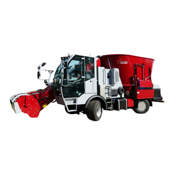
Page 40: Product Description
Product description Product description This chapter contains: comprehensive information on the design of the machine, the designations of the individual components and actuators. If possible, read this chapter while directly at the machine. This is the best way to become familiar with the machine. - Page 41 Product description Fig. 4-2: Entire machine - right side of the machine Assembly hatch Headlight Ejector hood Engine compartment Exterior mirror right (10) Cross conveyor Work lights (11) Counter blade Loading arm (12) Mixing hopper Profiled roller with guard V-MIX Drive Original Operating Manual...
- Page 42 Product description Fig. 4-3: Entire machine - left side of the machine (driver's side) Mixing hopper AdBlue tank Work lights Step Rear view camera Ladder, behind it: Switch cabinet Vehicle lighting, rear Hydraulic oil tank Fuel tank (10) Condenser + air conditioning Original Operating Manual V-MIX Drive...
-
Page 43: Intended Use
Product description Intended use The self-propelled mixer wagon Maximus Plus 11-1S/13N-1S/13H-1S/15-1S/17-1S: is a vertical mixer and intended exclusively for loading feeding stuff via the profiled roller and for crushing, homogeneously mixing, transporting and discharging feeding stuff used in animal husband- ... -
Page 44: Safety Devices And Guards
Product description Safety devices and guards This chapter provides an overview of the safety devices and guards and the arrangement of the correctly installed guards in the safety position. Risks of personal injury from crushing, entanglement and catching may arise when WARNING moving parts of the machine are unprotected during operation! ... -
Page 45: Danger Area And Hazard Areas
Product description Danger area and hazard areas The danger area is the area in and/or around a machine where dangerous situations may arise that will affect the health or safety of a person. No one is allowed to stay inside the danger area: ... -
Page 46: Danger Area Platform
Product description 4.4.1 Danger area platform Mortal danger if riding along on the platform behind the driver's cab! DANGER Hitching a ride on the platform is prohibited. Immediate and severe injury, including death, may result from falls or from becoming crushed. -
Page 47: Technical Data
Product description Technical data Type Unit 11-1S 13N-1S 13H-1S 15-1S 17-1S Capacity: 11.2 12.2 13.2 14.2 16.2 Number of cows: 76-85 82-91 95-105 102-112 115-131 Engine: FPT, 4 cylinders, up to 128 kW / 174 HP Overall length: 7740 7850 7770 7900 8280... -
Page 48: Type Plate And Ce Mark Type Plate And Ce Mark
Product description Type plate and CE mark Type plate and CE mark The illustrations below show the arrangement of type plate, chassis no. (machine number) and CE mark. The entire identification constitutes a legal document and may not be altered or disfigured beyond recognition. -
Page 49: Conformity
Product description Conformity The machine is in conformity with all general health and safety requirements stipulated in the directives and standards listed below: Machinery Directive 2006/42/EC EMC Directive 2014/30/EU EN 349:1993+A1:2008 EN 703:2004+A1:2009 EN ISO 4254-1:2015 ... -
Page 50: Design And Function
Design and function Design and function The following chapter contains information about the design of the machine and the function of its indi- vidual components. Some illustrations show the machines fitted with special equipment. Special equip- ment options are marked in this operating manual and available for an extra price. Driver's cab - overview This overview is intended to provide a quick guide to the driver's cab. -
Page 51: Cab Door
Design and function 5.1.1 Cab door Mortal danger if falling out of the driver’s seat inadvertently while driving with the cab DANGER door open! Driving the machine with the cab door open is prohibited. Risk of injury to humans/animals if the cab door is opened and closed in a careless WARNING manner! Before opening/closing the cab door, make sure that no person/animal is in the swivel range... -
Page 52: Opening The Cab Door
Design and function 5.1.1.2 Opening the cab door From the outside: Keep people/animals away from the swivel range of the cab door. Open the door lock (1) using the door key. Push in the door lock (1) and open the door. Fig. -
Page 53: Closing The Cab Door
Design and function 5.1.1.3 Closing the cab door Risk of injury and accidents to humans/animals by inadvertently opening a not WARNING properly closed cab door while driving! Never close the cab door in a careless or uncontrolled manner. Risks from unauthorized use of the machine! WARNING Lock the door lock when parking the machine and leaving it unattended. -
Page 54: Opening The Door Window
Design and function 5.1.1.4 Opening the door window Risk of injury to humans/animals if the door window is opened and closed in a care- WARNING less manner! Before opening and closing the door window, make sure that no person/animal is in the swivel range of the door window. -
Page 55: Driver's Seat
Design and function 5.1.2 Driver's seat Depending on the selected equipment option, the machine is fitted with a mechanically cushioned or an air-sprung driver's seat. The driver’s seat can be adjusted to the specific shape of the driver's body. It is possible to adjust: ... -
Page 56: Mechanically Cushioned Driver's Seat
Design and function 5.1.2.1 Mechanically cushioned driver's seat Figure not matching the original Fig. 5-10: Mechanically cushioned driver's seat (1) Back extension (headrest): Adjust the height of the back extension by extend- ing/retracting it. To remove the headrest, pull it up and off. Give the headrest a tug so as to pull it past the end stop. - Page 57 Design and function (3) Backrest adjustment: Pull the locking lever (1) up and adjust the backrest by exerting pressure on/relieving pressure from the backrest at the same time. Once locked into place, the backrest must not be able to move into any other position. Fig.
-
Page 58: Air-Suspended Driver's Seat (Special Equipment)
Design and function 5.1.2.2 Air-suspended driver's seat (special equipment) Fig. 5-16: Air-suspended driver's seat (1) Headrest: Adjust the height of the headrest by extend- ing/retracting it. Adjust the inclination by tilting the headrest. To remove the headrest, pull it up and off. Give the headrest a tug so as to pull it past the end stop. - Page 59 Design and function (3) Lumbar support: Pressing the front (1) and rear (2) switch leads to an individual adjustment of the bulge in the lower and upper area of the backrest cushion. When the bulge of the backrest cushion stops changing when you press the “+”...
- Page 60 Design and function Fig. 5-21: Longitudinal adjustment (8) Adjustment of the seat depth Pull the button (1) up and adjust the seating surface by sliding it forward/backward at the same time. Fig. 5-22: Adjustment of the seat depth Original Operating Manual V-MIX Drive...
-
Page 61: Steering Wheel
Design and function 5.1.3 Steering wheel The height and inclination of the steering wheel are infinitely variable. Risks in case of brief distractions! DANGER Never adjust the position the steering wheel while driving (risk of accident). The steering column (2) is kept in the vertical position by spring action. -
Page 62: Dashboard - Overview
Design and function 5.1.5 Dashboard – overview This overview is intended to help you quickly familiarize yourself with the instruments, the warning and indicator lights and the controls found on the dashboard. Fig. 5-25: Dashboard Warning and indicator lights Display with running time meter Speedometer Indicator for hydraulic oil temperature Buttons (not assigned) -
Page 63: Instruments
Design and function 5.1.5.1 Instruments The instruments on the dashboard indicate the operating states of the machine. 5.1.5.1.1 Speedometer Indicates the current rate of speed at which you are trav- eling. Fig. 5-26: Speedometer 5.1.5.1.2 Indicator for fuel reserve The indicator shows the current fill level of the fuel tank between E and F. -
Page 64: Running Time Meter
Design and function 5.1.5.1.3 Running time meter The running time meter keeps track of the operating hours of the diesel engine. The operating hours indicate the time until the next scheduled maintenance. Fig. 5-28: Time/operating hours 5.1.5.1.4 Indicator for hydraulic oil temperature The indicator for the hydraulic oil temperature displays the temperature of the hydraulic oil. -
Page 65: Tachometer
Design and function 5.1.5.1.5 Tachometer Indicates the current engine speed. Fig. 5-30: Tachometer V-MIX Drive Original Operating Manual... -
Page 66: Warning And Indicator Lights
Design and function 5.1.5.2 Warning and indicator lights The warning and indicator lights indicate certain functions/faults. Some of the warning and indicator lights listed here are part of specific machine model options or included as special equipment. For a description of the warnings related to the warning and indicator lights, refer to the specified page numbers (e. -
Page 67: Indicator Lights Of Lighting And Turn-Signal Indicator System
Design and function 5.1.5.2.2 Indicator lights of lighting and turn-signal indicator system Low beam page 129 Comes on if the low beam is switched on. High beam page 130 Comes if the high beam or switched on or the headlight flashes is being actuated. Turn-signal indicator system page 130 Flashes if the turn-signal indicator system is switched on. -
Page 68: Controls
Design and function 5.1.5.3 Controls Combo switch for turn-signal indicator, high beam, headlight flasher, windshield wiper/windshield washer page 130 / fluid front and horn Turn-signal indicator, high beam, and headlight flasher Windshield wiper/windshield washer fluid front Horn Hazard warning flasher page 131 Hazard warning flasher on/off... -
Page 69: Control Panel - Overview
Design and function 5.1.6 Control panel – overview The control panel houses various controls and warning lights. Some of the controls listed here are part of specific machine model options or included as special equipment. 5.1.6.1 Controls Windshield wipers page 132 Switch position 0: Switch wipers off. - Page 70 Design and function Operating mode selector switch see page 77 Select operating modes: = Loading = Feeding = Transport = Diagnostic mode Multi-function lever see page 82 Execute the functions of the machine. Hand throttle lever for diesel engine see page 72 Set the engine speed of the diesel engine.
-
Page 71: Operating Monitor Of The Diesel Engine
Design and function 5.1.7 Operating monitor of the diesel engine This chapter describes the different indicators as well as the warning and indicator lights that may light up on the dashboard or on the information and operating terminal to indicate the operating states of the diesel engine. -
Page 72: Warning Light Charge Check/Alternator
Design and function 5.1.7.3 Warning light charge check/alternator If this warning light is on, the batteries are not being charged. The warning light comes on when the ignition is switched on. It must turn off again once the diesel engine has started up. If the warning light is on during travel, the batteries are no longer being charged by the alternator. -
Page 73: Coolant Level
Design and function 5.1.7.3.3 Coolant level If the warning light (1) in the cockpit comes on, the coolant level is too low. The warning light in the cockpit comes on when the ignition is switched on. It must turn off again once the diesel engine has started up. -
Page 74: Indicator And Warning Lights For The Operating States Of The Hydraulic System
Design and function 5.1.9 Indicator and warning lights for the operating states of the hydraulic system 5.1.9.1 Warning light hydraulic oil temperature If the warning light comes on, the coolant temperature is too high. A fault has occurred if: the warning light fails to go out after a few seconds when you switch on the ignition, ... -
Page 75: 5.1.10.1 Heating Or Cooling The Cab Compartment
Design and function 5.1.10.1 Heating or cooling the cab compartment Risk of catching a cold from cold streams of air while the cab compartment is being WARNING cooled! Do not cool down the air in the cab by more than approx. 5 - 8°C relative to the outside temperature. - Page 76 Design and function Heating the cab compartment Turn the control dial (3) to set the desired tempera- ture. Turn the control dial (3) clockwise as far as it will go to attain the greatest possible heat output. Turn the blower control (1) to one of the stages between 0 and 3.
-
Page 77: Selecting Operating Modes
Design and function 5.1.11 Selecting operating modes You select the 4 possible operating modes “Loading”, “Feeding”, Transport” and “Diagnostics and set- tings” using the rotary switch “Operating modes". Depending on the operating mode you selected, the information and operating terminal will show the home screen “Loading”, “Feeding”, “Transport”... -
Page 78: Operating Mode "Loading
Design and function 5.1.11.1 Operating mode “Loading” Select the Operating mode “Loading” if you want to load fodder components with the profiled roller. When set to Operating mode “Loading”, the machine can be moved with a driving speed between 0 - 12 km/h at the maximum speed of the diesel engine (1800 min ) using the throttle pedal. -
Page 79: Operating Mode "Feeding
Design and function 5.1.11.2 Operating mode “Feeding” Select the Operating mode “Feeding” if you want to discharge fodder. In Operating mode “Feeding”, the speed of the diesel engine is limited to approx. 1800 min except when you set the mixing auger(s) to rapid speed (in which case it is 2000 min ... -
Page 80: Operating Mode "Transport
Design and function 5.1.11.3 Operating mode “Transport” Select the Operating mode “Transport” if you want to make transport trips. In Operating mode “Transport”, the speed of the diesel engine is limited to approx. 1800 min . (Eco mode: 1800 min , which will be lowered once the driving speed has been reached (exact figure depends on the equipment).) ... -
Page 81: 5.1.11.4 Operating Mode "Diagnostics, Settings And Information
Design and function 5.1.11.4 Operating mode “Diagnostics, settings and information” Select the operating mode “Diagnostics, settings and information” if you want to adjust settings and/or perform fault diagnostics. Set the selector switch (2) to position "4" (diagnos- tics, settings and information). ... -
Page 82: Multi-Function Lever
Design and function 5.1.12 Multi-function lever This chapter describes the machine functions that can be executed using the multi-function lever. The assignments of the buttons on the multi-function lever vary with the operating mode you selected. The function that is currently being executed will stop in the neutral position. ... -
Page 83: 5.1.12.1 Multi-Function Lever - Mode 1: Loading
Design and function 5.1.12.1 Multi-function lever – mode 1: Loading Fig. 5-47: Multi-function lever – mode 1 (loading) Loading on/off Reverse loading Adjust elevator speed by +5%. Raise loading arm Adjust elevator speed by -5%. Lower loading arm Protective cover open/closed Travel direction of traction drive Reverse profiled roller (10) Rear button (red): error acknowledgment... -
Page 84: 5.1.12.2 Multi-Function Lever - Mode 2: Feeding
Design and function 5.1.12.2 Multi-function lever – mode 2: Feeding Fig. 5-48: Multi-function lever – mode 2 (feeding) Preselect gate 1 Shift cross conveyor to the right Preselect gate 2 Raise loading arm Preselect gate 3 Shift cross conveyor to the left Open/close discharge opening (10) Lower loading arm Discharge cross conveyor on the right... -
Page 85: 5.1.12.3 Multi-Function Lever - Mode 3: Transport
Design and function 5.1.12.3 Multi-function lever – mode 3: Transport Fig. 5-49: Multi-function lever – mode 3 (transport) Travel direction of traction drive V-MIX Drive Original Operating Manual... -
Page 86: Information And Operating Terminal
Design and function 5.1.13 Information and operating terminal The information and operating terminal and its screens are organized as follows. Fig. 5-50: Information and operating terminal Pos. Name Description Display Show the selected area. Selection buttons Select or switch on/off functions and adjust speed in 5% increments. Mode 1, 2, 3: Adjust mixer speed. -
Page 87: 5.1.13.1 Mode 1 - Loading
Design and function 5.1.13.1 Mode 1 – Loading You select the functions by using the selection buttons and the control dial. Fig. 5-51: Mode 1 - Loading Pos. Name Description Mixing auger Shows the mixer speed in %. Green: Seat is occupied. Seat contact switch Red: Seat is not occupied. - Page 88 Design and function Fig. 5-52: Mode 1 - Loading Pos. Name Description Mixing auger on/off Switch mixing auger on/off. Indicates if the mixing auger rapid speed is switched on or off. Mixing auger rapid speed Highlighted in green: Mixing auger rapid speed is switched on. Highlighted in blue: Mixing auger rapid speed is switched off.
-
Page 89: 5.1.13.2 Mode 2 - Feeding
Design and function 5.1.13.2 Mode 2 – Feeding You select the functions by using the selection buttons and the control dial. Fig. 5-53: Mode 2 - Feeding Pos. Name Description Mixing auger Shows the mixer speed in %. Seat contact switch Green: Seat is occupied. -
Page 90: 5.1.13.3 Mode 3 - Transport
Design and function 5.1.13.3 Mode 3 – Transport Fig. 5-54: Mode 3 - Transport Pos. Name Description Mixing auger Shows the mixer speed in %. Green: Seat is occupied. Seat contact switch Red: Seat is not occupied. Coolant temperature Shows the current coolant temperature. Display Shows the time and the speed. -
Page 91: 5.1.13.4 Mode 4 - Diagnostics, Settings And Information
Design and function 5.1.13.4 Mode 4 – Diagnostics, settings and information 5.1.13.4.1 Home screen The home screen in Diagnostics, settings and information mode shows all functions that can be executed in this mode. You select the functions by using the control dial. Fig. -
Page 92: 5.1.13.4.1.1 Diagnostics
Design and function 5.1.13.4.1.1 Diagnostics Fig. 5-56: Diagnostics, settings and information - diagnostics Pos. Name Description Status of traction drive Switch to the “Status of traction drive” menu. Inputs of traction drive Switch to the “Inputs of traction drive” menu. Outputs of traction drive Switch to the “Outputs of traction drive”... -
Page 93: Status Of Traction Drive
Design and function 5.1.13.4.1.1.1 Status of traction drive Fig. 5-57: Diagnostics, settings and information – diagnostics – status of traction drive Pos. Name Description Active/error Shows the current status of the traction drive. No error No error indicated for “Status of traction drive”. Power-reduced driving mode The machine operates only in power-reduced driving mode. -
Page 94: Inputs Of Traction Drive
Design and function 5.1.13.4.1.1.2 Inputs of traction drive Fig. 5-58: Diagnostics, settings and information – diagnostics – inputs of traction drive Pos. Name Description The sensor is OK. Sensor status The sensor is outside of the tolerance range and reports an Error error (e.g. -
Page 95: Outputs Of Traction Drive
Design and function 5.1.13.4.1.1.3 Outputs of traction drive Fig. 5-59: Diagnostics, settings and information – diagnostics – outputs of traction drive Pos. Name Description The sensor is OK. Sensor status The sensor is outside of the tolerance range and reports an Error error (e.g. -
Page 96: Machine Control
Design and function 5.1.13.4.1.1.4 Machine control Fig. 5-60: Diagnostics, settings and information – diagnostics – machine control Pos. Name Description The machine control is OK. Status Error The sensor has reported an error. List Designation of sensors, valves and potentiometers. Original Operating Manual V-MIX Drive... -
Page 97: Status Of Hydraulic Oil Filters
Design and function 5.1.13.4.1.1.5 Status of hydraulic oil filters Fig. 5-61: Diagnostics, settings and information – diagnostics – status of hydraulic oil filters Pos. Name Description The filter operates properly. The differential pressure sensor on the filter has reported an Status error, i.e. -
Page 98: 5.1.13.4.1.2 Settings
Design and function 5.1.13.4.1.2 Settings Fig. 5-62: Diagnostics, settings and information - settings Pos. Name Description Time Switch to the “Time” menu. Automatic extraction unit Switch to the “Automatic extraction unit” menu. Fan reversal unit Switch to the “Fan reversal unit” menu. Language Switch to the “Language”... -
Page 99: Time
Design and function 5.1.13.4.1.2.1 Time Fig. 5-63: Diagnostics, settings and information – settings – time Pos. Name Description Time Set the time. V-MIX Drive Original Operating Manual... -
Page 100: Automatic Extraction Unit
Design and function 5.1.13.4.1.2.2 Automatic extraction unit The automatic extraction unit has been preset at the factory and should only be changed after consulting the manufacturer or by expert personnel. Fig. 5-64: Diagnostics, settings and information – settings – automatic extraction unit Pos. -
Page 101: Automatic Fan Reversal Unit
Design and function 5.1.13.4.1.2.3 Automatic fan reversal unit Fig. 5-65: Diagnostics, settings and information – settings – automatic fan reversal unit (optional) Pos. Name Description Automatic On/Off Switch automatic extraction unit on/off (if present). Interval in min. Specify the interval at which reversal is repeated. Reversal duration in s. -
Page 102: Language
Design and function 5.1.13.4.1.2.4 Language Fig. 5-66: Diagnostics, settings and information – settings – language Pos. Name Description Language selection Select the language by pushing and turning the encoder. Original Operating Manual V-MIX Drive... -
Page 103: Mixer Speed
Design and function 5.1.13.4.1.2.5 Mixer speed Fig. 5-67: Diagnostics, settings and information – settings – mixer speed Pos. Name Description Reduces the speed of the mixing auger by a specified value (specifica- tion in percent) while the profiled roller is switched on. Reduction of the mixer speed Presetting: in percent with the profiled... -
Page 104: 5.1.13.4.1.3 Information
Design and function 5.1.13.4.1.3 Information Fig. 5-68: Diagnostics, settings and information - information Pos. Name Description Software versions Shows the current software versions. Original Operating Manual V-MIX Drive... -
Page 105: 5.1.13.5 Error Notifications
Design and function 5.1.13.5 Error notifications 5.1.13.5.1 Error coolant Fig. 5-69: Error coolant Pos. Name Description Coolant level low! Warning coolant Too little coolant in the system. 5.1.13.5.2 Error notification, cover The warning “Protective cover profiled roller not closed” appears if you change from mode 1 to mode 2 or 3 without having closed the protective cover. -
Page 106: 5.1.13.5.3 Error Notification, Loading Arm Position - Loading Arm Too High
Design and function 5.1.13.5.3 Error notification, loading arm position – loading arm too high The warning “Loading arm not in transport position” appears if you switch from mode 2 to mode 3 with the loading arm not set to the transport position. Fig. -
Page 107: 5.1.13.5.4 Error Notification, Loading Arm Position - Loading Arm Too Low
Design and function 5.1.13.5.4 Error notification, loading arm position – loading arm too low The warning “Loading arm not in transport position” appears if you switch from mode 2 to mode 3 with the loading arm not set to the transport position. Fig. -
Page 108: 5.1.13.5.5 Error Notification, Cross Conveyor Center Position
Design and function 5.1.13.5.5 Error notification, cross conveyor center position The warning “Cross conveyor not in center position” appears if you switch from mode 2 to mode 1 or 3 with the cross conveyor not set to the center position Fig. -
Page 109: 5.1.13.5.7 Error Notification, Hc Burn-Off Urea, Scr Catalytic Converter
Design and function 5.1.13.5.7 Error notification, HC burn-off UREA, SCR catalytic converter Fig. 5-75: Error, HC burn-off UREA, SCR catalytic converter Pos. Name Description Burn off remnants of HC (hydrogen remnants). HC burn-off SCR cata- The message will disappear when the process is complete. This may take lytic converter up to 60 minutes. -
Page 110: 5.1.13.5.8 Adblue Fill Level
Design and function 5.1.13.5.8 AdBlue fill level Fig. 5-76: AdBlue fill level Pos. Name Description Reserve lev- The indicator comes on and the signaling device beeps 1x el 1 per minute. AdBlue fill level Reserve lev- The indicator comes on and the signaling device beeps el 2 continuously. -
Page 111: Adblue Quality Warning Level 1
Design and function 5.1.13.5.9 AdBlue quality warning level 1 Fig. 5-77: AdBlue quality warning level 1 Pos. Name Description AdBlue quality Notification, but no reduction of power yet. warning level 1 The error must be reset by a specialist dealer! 5.1.13.5.10 AdBlue quality warning level 2 Fig. -
Page 112: Adblue Quality Warning Level 3
Design and function 5.1.13.5.11 AdBlue quality warning level 3 Fig. 5-79: AdBlue quality warning level 3 Pos. Name Description AdBlue quality The machine is reduced step by step in idling speed. warning level 3 The error must be reset by a specialist dealer! 5.1.13.5.12 AdBlue equipment warning level 1 Fig. -
Page 113: Adblue Equipment Warning Level 2
Design and function 5.1.13.5.13 AdBlue equipment warning level 2 Fig. 5-81: AdBlue equipment warning level 2 Pos. Name Description Warning with reductions in power and speed, which are increased in incre- AdBlue equipment ments. warning level 2 This error can have different causes, e.g. a pressure drop of the AdBlue. The error must be reset by a specialist dealer! V-MIX Drive Original Operating Manual... -
Page 114: Adblue Equipment Warning Level 3
Design and function 5.1.13.5.14 AdBlue equipment warning level 3 Fig. 5-82: AdBlue equipment warning level 3 Pos. Name Description The machine is reduced step by step in idling speed. AdBlue equipment warning level 3 This error can have different causes, e.g. a pressure drop of the AdBlue. The error must be reset by a specialist dealer! Original Operating Manual V-MIX Drive... -
Page 115: Diesel Engine
Design and function Diesel engine 5.2.1 Starting the diesel engine Risk of poisoning from exhaust gases if the diesel engine is running in unventilated WARNING or closed rooms or similar spaces! Before starting up or operating the diesel engine in a closed room, connect the exhaust pipe to a designated venting system. - Page 116 Design and function tion. Do not actuate the starter for more than 20 seconds, as it may otherwise overheat. If the diesel engine fails to start at the first try, wait for at least 1 minute before making another attempt to start the engine. If the diesel engine fails to start after 2 attempts, please refer to the “Troubleshooting”...
-
Page 117: Warming Up The Diesel Engine
Design and function 5.2.2 Warming up the diesel engine Risk of engine failure! CAUTION Let the diesel engine warm up without load and at an engine speed between 1000 min – 1200 min for 1 – 2 minutes to ensure that the diesel engine is properly lu- bricated. -
Page 118: Starting The Diesel Engine Using A Jumper Battery
Design and function 5.2.5 Starting the diesel engine using a jumper battery Risk of explosion from battery fumes caused by spark formation and open flames in DANGER the vicinity of batteries! Avoid spark formation and open flames in the vicinity of batteries. ... -
Page 119: Tow-Starting The Diesel Engine
Design and function 5.2.6 Tow-starting the diesel engine Tow-starting the diesel engine is not possible as the machine is equipped with a hydrostatic traction drive. 5.2.7 Shutting off the diesel engine Risk of engine failure from overheating and accelerated wear of engine components CAUTION after an extended period of high diesel engine loads! Continue to run the diesel engine at an engine speed of 1000 min... -
Page 120: Operating The Diesel Engine In The Winter
Design and function 5.2.8 Operating the diesel engine in the winter Risks from revving up the engine abruptly when using so-called “engine starter WARNING spray” (e.g. start pilot)! Never use an engine starter spray to start up the diesel engine. ... -
Page 121: Drive Mode
Design and function Drive mode The machine comes standard with a hydrostatic front-wheel drive. Four-wheel drive is available as spe- cial equipment. The throttle pedal is used to continuously accelerate and decelerate the machine. The further you press down the throttle pedal, the faster the driving speed becomes. The driving speed that can be achieved depends on the selected operating mode (loading, feeding, transport), the position of the throttle pedal (engine speed), the tractive resistance and the consumption of hydrostatic power required for operating the working hydraulics / steering. -
Page 122: Driving Forward
Design and function 5.3.1 Driving forward Enable forward driving: Release the parking brake. Push up the FNR switch (1). The function "Forward driving" is enabled. The indicator light "Travel direction forward" (2) lights up on the dashboard. Check the danger area of the machine. Keep people/animals away from the danger area of the machine before starting to drive forward. -
Page 123: Driving In Reverse
Design and function 5.3.2 Driving in reverse Risks to humans/animals while driving the machine in reverse! DANGER Before driving in reverse, check the danger area next to and behind the machine. Do not move the machine unless no person/animal is in the danger area of the machine. Enabling driving in reverse: Release the parking brake. -
Page 124: Decelerating And Stopping The Machine
Design and function 5.3.3 Decelerating and stopping the machine While driving, you can brake and stop the machine using the throttle pedal and, if nec- essary, the brake pedal. The brake system actuated by the brake pedal acts on the front and the rear axle. The front and the rear axles are fitted with hydraulic brakes. -
Page 125: Parking Brake (Hand Brake)
Design and function 5.3.4 Parking brake (hand brake) Made up of a spring-loaded cylinder and a spring, the parking brake is a spring-loaded brake that acts on the front axle. The parking brake is released by pressing hydraulic oil into the spring-loaded cylinder at a hydraulic oil pressure of approximately 30 bar. -
Page 126: Switching Four-Wheel Drive On And Off (Optional)
Design and function 5.3.5 Switching four-wheel drive on and off (optional) The rear-wheel drive cannot be activated unless four-wheel steering is activated. The rear-wheel drive cannot be activated unless the machine is standing still. If you press the button while the machine is still rolling, the “Four-wheel drive” button will flash orange (at 1 Hz) until the machine is at a standstill and the valve for four-wheel drive has switched. -
Page 127: Differential Lock
Design and function 5.3.6 Differential lock When switched on, the differential lock ensures that the drive wheel with less traction is prevented from slipping. The differential lock stiffens the drive train and prevents rpm compensation. If the drive wheels rotate unevenly on loose underground, turn the differential lock on. ... -
Page 128: Steering
Design and function 5.3.7 Steering The machine comes standard with a front wheel steering system. A hydraulic steering system reduces the force that is required to turn the steering wheel when steering with the machine at a standstill and while maneuvering or driving at low driving speeds. Four-wheel steering is available as special equipment. -
Page 129: Lighting And Visibility
Design and function Lighting and visibility 5.4.1 Switching the sidelight or headlight on and off Risk of injury during travel on public roadways from driving with the sidelight WARNING switched on! Never drive with the sidelight switched on. The sidelight is not bright enough to sufficiently light the road or make the machine visible to other traffic participants. -
Page 130: Turn-Signal Indicator, High Beam, And Headlight Flasher
Design and function 5.4.2 Turn-signal indicator, high beam, and headlight flasher You switch on the turn-signal indicator, the high beam, and the headlight flasher by using the combo switch. The turn-signal indicator system works only with the ignition switched on. ... -
Page 131: Hazard Warning Flasher
Design and function 5.4.3 Hazard warning flasher The hazard warning flasher is used to alert other traffic participants to your machine in dangerous situa- tions. High risk of accident if the machine breaks down in a public place! DANGER Always use the hazard warning flasher and the breakdown triangle to alert other traffic par- ticipants to the inoperative machine. - Page 132 Design and function Windshield wiper - front window You actuate the windshield wiper and the automatic wiping/washing system of the front window by using the rotary switch of the combo switch. Interval wiping Turn the rotary switch (2) in the direction of the arrow (3) until it engages in position “J”.
-
Page 133: Mirrors
Design and function 5.4.4.2 Mirrors The machine is fitted with two large exterior mirrors that are located on the left and the right side. Both sides of the machine also house a close-proximity mirror, while a “blind spot” mirror is found on the right side of the machine. - Page 134 Design and function Switching on the exterior mirror heating Set the toggle switch "Mirror heating” to the “ON” position (2). The mirror heating for all mirrors is switched on, and the indicator light in the toggle switch is lit. Fig.
-
Page 135: Rear View Camera
Design and function 5.4.4.3 Rear view camera When you change the travel direction from “Forward” to “Backward”, the additional display will automati- cally show the image captured by the rear view camera. The rear view camera affords you a view of the danger area behind the machine. Risks to third parties/animals/objects when driving in reverse without a clear and di- DANGER rect view of the area behind the machine from the driver's seat! -
Page 136: Loading Arm
Design and function Loading arm 5.5.1 Raising/lowering the loading arm To raise and lower the loading arm, move the multi-function lever out of the neutral posi- tion and hold it in place until the loading arm has reached the desired height. When released, the multi-function lever automatically returns to the neutral position. -
Page 137: Setting The Loading Arm To The Transport Position
Design and function 5.5.2 Setting the loading arm to the transport position Before you can select “Transport” mode, you need to raise or lower the loading arm to the necessary minimum height. Only if the loading arm is at the necessary minimum height can you: ... -
Page 138: Profiled Roller And Elevator
Design and function Profiled roller and elevator 5.6.1 Switching profiled roller and elevator on and off The profiled roller and the elevator can only be switched on/off in mode 1 (loading). The drives powering the profiled roller and the elevator are interconnected via the hy- draulic control. -
Page 139: Adjusting The Drive Speed Of The Profiled Roller
Design and function Switching on profiled roller and elevator: Keep people/animals away from the danger area of the profiled roller. Press button (1) twice. Button (1) lights up red. The profiled roller and the elevator are switched on and the fields “Profiled roller and elevator”... -
Page 140: Adjusting The Belt Speed Of The Elevator
Design and function 5.6.3 Adjusting the belt speed of the elevator The belt speed of the elevator can only be adjusted in mode 1 (loading). When loading fodder components that tend to form dust, reduce the drive belt speed of the elevator. -
Page 141: Opening/Closing The Guard On The Profiled Roller
Design and function 5.6.4 Opening/closing the guard on the profiled roller The guard of the profiled roller can only be opened/closed in mode 1 (loading). Risks to humans and animals from the sharp-edged profiled roller if transport trips DANGER are made with the guard open! Close the open guard of the profiled roller before setting out on transport trips. -
Page 142: Reversing Profiled Roller And Elevator
Design and function 5.6.5 Reversing profiled roller and elevator The profiled roller and the elevator can only be reversed in mode 1 (loading). Select the drive direction “Reverse” to convey out previously loaded fodder components from the area of the profiled and the elevator. Reversing the profiled roller: Keep people/animals away from the danger area of the profiled roller. - Page 143 Design and function Opening the dosing gate: Keep people/animals away from the danger area of the dosing gate. Press the necessary button (1, 2 or 3). The button lights up red. Press the thumb wheel (4) up repeatedly until the display (5) reaches the desired door 0 = gate closed 50 = gate opened halfway...
-
Page 144: Cross Conveyor
Design and function Cross conveyor 5.7.1 Switching the conveyor on and off The conveyor can only be switched on/off in mode 2 (feeding). The cross conveyor can be operated in two drive directions. Depending on the selected drive direction, the fodder will be discharged on the right or the left side of the machine. Discharging the fodder on the left side of the ma- chine: Keep people/animals away from the danger area of... -
Page 145: Adjusting The Belt Speed Of The Cross Conveyor
Design and function 5.7.1.1 Adjusting the belt speed of the cross conveyor The belt speed of the cross conveyor can only be adjusted in mode 2 (feeding). The set belt speed defines the lateral distance (throw distance) at which the fodder is deposited next to the machine. -
Page 146: Shifting The Cross Conveyor To The Right Or Left (Optional)
Design and function 5.7.2 Shifting the cross conveyor to the right or left (optional) The cross conveyor can only be shifted in mode 2 (feeding). The hydraulic side shift of the cross conveyor can be used to shift the cross conveyor to the right or left by 300 mm (special equipment). -
Page 147: Platform
Design and function Platform Mortal danger if riding along on the platform behind the driver's cab! DANGER Hitching a ride on the platform is prohibited. Immediate and severe injury, including death, may result from falls or from becoming crushed. The operator must not be on the platform (1) unless they can be sure that no one will move the machine. -
Page 148: Mixing Auger
Design and function Mixing auger 5.9.1 Switching the mixing auger on and off The mixing auger can only be switched on/off in modes 1 (loading) and 2 (feeding). The mixing auger can be switched on/off using the key- pad or the information and operating terminal. Switching the mixing auger on using the keypad: Press button (1) on the keypad. -
Page 149: Adjusting The Drive Speed Of The Mixing Auger
Design and function 5.9.2 Adjusting the drive speed of the mixing auger Turn the control dial (2) until the display shows the value (1) of the desired drive speed (in %). Displayed value 0% = mixing auger stops rotating (0 min ... -
Page 150: Switching Rapid Speed For The Mixing Auger On And Off
Design and function 5.9.3 Switching rapid speed for the mixing auger on and off Rapid speed for the mixing auger can only be switched on/off in modes 1 (loading) and 2 (feeding). To throw any remaining fodder off the mixing auger at the end of the feeding process and to empty the mixing hopper completely, switch the drive speed of the mixing auger briefly to rapid speed in the operating mode “Feeding”. -
Page 151: Switching Cleaning Mode For The Mixing Auger On
Design and function 5.9.4 Switching cleaning mode for the mixing auger on Cleaning mode can only be switched on in mode 2 (feeding). Cleaning requires that the mixing auger be switched on (see Chapter 5.9.1 “Switching the mixing auger on and off”). Activating rapid speed causes the diesel engine to run at 2000 min for 10 seconds. -
Page 152: Reverse The Drive Direction Of The Mixing Auger
Design and function 5.9.5 Reverse the drive direction of the mixing auger If the fodder is backed up at the discharge opening or if the mixing auger is jammed me- chanically, reverse the drive direction of the mixing auger. Press button (1). ... -
Page 153: Cutting Blades Of The Mixing Auger
Design and function 5.11 Cutting blades of the mixing auger Housed in the mixing hopper and equipped with cutting blades (2), the powered mixing auger (1) reduces and mixes the fodder components filled into the hopper. The discharge arm (3) in the lower region of the mixing auger assures a quick and consistent discharge of the mixed fodder components. -
Page 154: Counter Blade
Design and function 5.12 Counter blade The use of the counter blade (1) allows for a finer reduc- tion and swifter mixing of the fodder components filled into the mixing hopper. The counter blade: is used, for instance, for the reduction and mixing of round or square bales, ... -
Page 155: Weighing System
USB stick and PC interface. BvL Dairy Feeder with PDA and Internet connection Fig. 5-146: Weight probes Observe the supplied operating manual of the weighing equipment. Fig. 5-147: Weighing system... -
Page 156: Commissioning And National Traffic Regulations
Commissioning and national traffic regulations Commissioning and national traffic regulations This chapter contains information on how to put the machine into operation. Before putting the machine into operation, the operator is required to have read and understood the operating manual. ... -
Page 157: Traffic Regulations Applicable In Germany
Commissioning and national traffic regulations 6.1.1 Traffic regulations applicable in Germany Every machine that is supposed to travel on public roadways is required to have its own individual operating permit. This permit must be obtained from the registration office by submitting a TÜV certificate for the machine. -
Page 158: Securing The Machine Against Unintended Start-Up And Rolling Away
Commissioning and national traffic regulations Securing the machine against unintended start-up and rolling away Risks of personal injury from crushing, shearing, cutting, amputation, entrapment, WARNING winding up, entanglement, catching and impact may arise from interventions on the machine: if hydraulic functions are executed inadvertently or if work tools or parts of the machine are actuated while the diesel engine is running, ... -
Page 159: Use Of The Machine
Use of the machine Use of the machine When using the machine, observe the additional information provided in the chapters listed below: 2.2.2 “Responsibilities of the operator”, on page 14, 2.2.3 “Qualification of the personnel”, on page 15, ... -
Page 160: Loading The Mixer Wagon
Use of the machine Loading the mixer wagon Risks of personal injury due to crushing, cutting, entanglement, and entrapment may WARNING arise if improper loading of the mixing hopper results in inadvertent contact with the powered mixing auger! Use only the profiled roller or other suitable equipment to fill the mixing hopper. Suitable equipment includes: Tractor with front loader, Wheel/farmyard loader. -
Page 161: Recommended Order During Filling
Use of the machine Use the weighing system to load the mixing hopper accurately. The weighing system weighs the material contained in the mixing hopper. Once the fill quantity of a fodder component has been reached in the mixing hopper, the loaded fodder component can be conveyed out again from the area of the profiled roller and of the elevator (see Chapter 5.6.5 “Reversing profiled roller and elevator”, page 142). -
Page 162: Loading Silage From A Clamp Silo
Use of the machine 7.1.2 Loading silage from a clamp silo Remove the silage you are extracting from the clamp of a clamp silo by moving from top to bottom. Set the hand throttle lever to full throttle so as to operate the diesel engine at its rated speed. - Page 163 Use of the machine Select operating mode "Loading” (see Chapter 5.1.11.1 “Operating mode “Loading””, page 78). Keep people/animals away from the danger area of the profiled roller. Open the guard of the profiled roller (see Chapter 5.6.4 “Opening/closing the guard on the profiled roller”, page 141).
-
Page 164: Loading Round Bales
Use of the machine 7.1.3 Loading round bales The round bales must be dropped off on the face side. Remove straps/nets/film from the round bales. Load the round bales from top to bottom. When loading bales of hay or straw, set the hand throttle lever such that the diesel en- gine is operated at an engine speed of 1600 min - 1800 min ... -
Page 165: Loading Square Bales
Use of the machine 7.1.4 Loading square bales Remove straps/nets/film from the square bales. Load square bales crosswise to the baling direction. When loading bales of hay or straw, set the hand throttle lever such that the diesel en- gine is operated at an engine speed of 1600 min - 1800 min ... -
Page 166: Loading Groats, Concentrated Feed, Brewer's Grains, And Other Types Of Fodder Components
Use of the machine 7.1.5 Loading groats, concentrated feed, brewer’s grains, and other types of fodder compo- nents When loading fodder components that tend to form dust (e.g. groats), reduce the drive speed of the profiled roller and the belt speed of the elevator. Select operating mode "Loading”... -
Page 167: Mixing Fodder Components
Use of the machine Mixing fodder components The mixing time varies with the type and the structure of the fodder components used and with the desired cut length of the feed mix. The mixing time for highly structured components that need to be cut is higher. ... -
Page 168: Discharging Fodder
Use of the machine Discharging fodder Risks to humans and animals from impact may arise if objects are flung out of the WARNING discharge opening or the cross conveyor while the fodder is being discharged! Keep people/animals away from the danger area before opening the discharge opening or switching on the cross conveyor. - Page 169 Use of the machine Select operating mode "Feeding” (see Chapter 5.1.11.2 “Operating mode “Feeding””, page 79). Keep people/animals away from the danger area of the cross conveyor. Use the hand throttle level to set the necessary engine speed for the diesel engine. The necessary engine speed depends on the drive power required for the machine.
-
Page 170: Removing Clogs
Use of the machine 7.3.1 Removing clogs Risks of personal injury from crushing, shearing, cutting, amputation, entrapment, WARNING winding up, entanglement, catching and impact may arise if: raised, unsecured parts of the machine lower or are lowered inadvertently, e. g. an open dosing gate, Before working in the area of raised machine parts, secure the parts from being lowered inadvertently. -
Page 171: Transport Trips
Transport trips Transport trips A transport trip is a journey to and from the location where the machine is used while loaded or unload- Also observe the information given regarding transport trips in chapter 2.4 “General safety instructions”, starting on page 17. ... - Page 172 Transport trips Risks of personal injury due to crushing, cutting, entanglement, and entrapment may WARNING arise if the profiled roller is running during transport trips! The profiled roller must be switched off during trips on public roads. Risks of personal injury from improper use of the machine may arise if the malfunc- WARNING tion of components, insufficient stability and inability to properly steer and brake the machine occur as a result!
-
Page 173: Cleaning, Maintenance And Repairs
Cleaning, maintenance and repairs Cleaning, maintenance and repairs When cleaning, servicing and repairing the equipment, observe the information provided in the following chapters: 2.2.2 “Responsibilities of the operator”, on page 14, 2.2.3 “Qualification of the personnel”, on page 15, ... -
Page 174: Cleaning
Cleaning, maintenance and repairs Cleaning Check every day to see if the machine and, in particular, the radiator, engine and engine hood require cleaning. Remove any fodder or dust that may have accumulated on the radiator, the engine, and the engine hood (risk of fire). -
Page 175: Lubricating
Cleaning, maintenance and repairs Lubricating Lubricate all bearing and lubrication points in accordance with the lubrication chart (see maintenance booklet). Remove dirt from the lubrication nipples. Use environmentally safe and biodegradable oils and greases as lubricants may enter feedstuffs or the soil! Contact your authorized farm equipment dealer for more infor- mation. -
Page 176: Lubrication Points On The Loading Arm
Cleaning, maintenance and repairs 9.2.1 Lubrication points on the loading arm Fig. 9-1: Lubrication points on the loading arm Pos. Lubrication point Quantity Lubricant Quantity Activity Interval Pivot point protective Total Nevastane Lubrication nip- 3 strokes every 50 Oh cover of profiled roller XMF2 ple/lubricate Deflection roller eleva-... -
Page 177: Lubrication Points On The Rear Cross Conveyor
Cleaning, maintenance and repairs 9.2.2 Lubrication points on the rear cross conveyor Fig. 9-2: Lubrication points on the rear cross conveyor Pos. Lubrication point Quantity Lubricant Quantity Activity Interval Total Nevastane Lubrication nip- Bearing for drive roller 3 strokes every 25 Oh XMF2 ple/lubricate Bearing for deflection... -
Page 178: Lubrication Points On The Side Elevator
Cleaning, maintenance and repairs 9.2.3 Lubrication points on the side elevator Fig. 9-3: Lubrication points on the side elevator Pos. Lubrication point Quantity Lubricant Quantity Activity Interval Bearing for deflection Total Nevastane Lubrication nip- 3 strokes every 25 Oh roller XMF2 ple/lubricate Total Nevastane... -
Page 179: Lubrication Points On The Front And Rear Axles
Cleaning, maintenance and repairs 9.2.4 Lubrication points on the front and rear axles Fig. 9-4: Lubrication points on the front and rear axles Pos. Lubrication point Quantity Lubricant Quantity Activity Interval 1x left Total Nevastane Lubrication nip- Axle journals, top every 50 Oh 3 strokes 1x right... -
Page 180: Other Lubrication Points On The Machine
Cleaning, maintenance and repairs 9.2.5 Other lubrication points on the machine Fig. 9-5: Other lubrication points on the Machine Pos. Lubrication point Quantity Lubricant Quantity Activity Interval Cylinder holder at Total Nevastane Lubrication nip- every 50 Oh 3 strokes loading arm XMF2 ple/lubricate Total Nevastane... -
Page 181: Maintenance Schedule
Cleaning, maintenance and repairs Maintenance schedule Follow the included maintenance booklet. Perform maintenance in a timely manner. The times, continuous services or maintenance intervals of any third-party documenta- tion are given priority. Checking and refilling Observe the operating manual included with the diesel engine regarding the service fluids. Severe functional defects and damage on the diesel engine or the hydraulic compo- CAUTION nents if service fluids are mixed up! -
Page 182: Refueling
Cleaning, maintenance and repairs 9.4.1 Refueling Monitor the fuel gage. Refuel at the latest when the fuel level is down to one third. Also observe the information given on diesel fuel in the chapter “Fuels, lubricants and coolants” included in the supplied operating manual of the diesel engine. ... -
Page 183: Adblue
Cleaning, maintenance and repairs 9.4.2 AdBlue Power reduction caused by low AdBlue fill level and/or failure to observe error mes- WARNING sage and warnings! Pay attention to the AdBlue fill level. Observe error messages and warnings (see Chapters 5.1.13.5.6 - 5.1.13.5.14). If the AdBlue tank is run dry completely, the power reduction needs to be reset by a dealer. -
Page 184: Topping Off Adblue
Cleaning, maintenance and repairs 9.4.2.2 Topping off AdBlue The AdBlue is large enough to hold two diesel fillings. This means that the AdBlue must be topped off with every other refueling. The AdBlue tank holds approximately 43 liters. Shut off the diesel engine. Turn off the ignition. -
Page 185: Working In The Engine Compartment
Cleaning, maintenance and repairs 9.4.3 Working in the engine compartment Risks from moving or hot engine parts inside the engine compartment! DANGER All work steps performed on the diesel engine or inside the engine compartment, e.g. checking and topping off service fluid levels, carry the risk of injury, scalding, acci- dent or fire! ... -
Page 186: Opening The Engine Compartment Cover
Cleaning, maintenance and repairs 9.4.3.1 Opening the engine compartment cover Scalding or burning injuries from hot coolant! DANGER Never open the engine compartment cover if steam or coolant is escaping. Risk of scalding! Wait until no more steam or coolant is escaping and let the diesel engine cool down before opening the engine compartment cover. -
Page 187: Closing The Engine Compartment Cover
Cleaning, maintenance and repairs 9.4.3.2 Closing the engine compartment cover Risk of accident if an improperly closed engine compartment cover opens in mid- WARNING travel! After closing the engine compartment cover, always verify that the locking mechanisms have engaged properly. ... -
Page 188: Opening The Assembly Hatch
Cleaning, maintenance and repairs 9.4.3.3 Opening the assembly hatch Scalding or burning injuries from hot coolant! DANGER Never open the assembly hatch if steam or coolant is escaping. Risk of scalding! Wait until no more steam or coolant is escaping and let the diesel engine cool down before opening the assembly hatch. -
Page 189: Diesel Engine Oil
Cleaning, maintenance and repairs 9.4.4 Diesel engine oil The grade of the diesel engine oil must conform to precisely defined specifications. We recommend us- ing “SAE 10W40” according to specification “API CJ-4 / ACEA E9”. Risk of engine failure! CAUTION Use only diesel oil specifications that have been approved for the diesel engine. -
Page 190: Checking The Engine Oil Level
Cleaning, maintenance and repairs 9.4.4.1 Checking the engine oil level It is normal for the diesel engine to consume engine oil. Oil consumption varies with the load to which the diesel engine is subjected. Check the engine oil level daily or at the beginning of every work day ... -
Page 191: Refilling Engine Oil
Cleaning, maintenance and repairs 9.4.4.2 Refilling engine oil Refill engine oil only in small portions. The engine oil level must never be above the upper marking. Otherwise, engine oil may be sucked into the exhaust system through the ventilation of the crankcase and enter the at- mosphere. -
Page 192: Changing Engine Oil And Filters
Cleaning, maintenance and repairs 9.4.4.3 Changing engine oil and filters Observe the chapter “Lubrication system” included in the operating manual supplied with the diesel engine. Properly dispose of waste oil and filters. If experiencing problems with disposal, contact your oil supplier. -
Page 193: Coolant
Cleaning, maintenance and repairs 9.4.5 Coolant The cooling system is filled with a special coolant and provides protection against corrosion and pitting on the cylinder sleeves all year round. Its antifreeze provides protection against temperatures as low as -35°C. Observe the various information on the topic of coolant (cooling liquid) that is provided in the respective chapters of the operating manual supplied with the diesel engine. -
Page 194: Refilling Coolant
Cleaning, maintenance and repairs 9.4.5.2 Refilling coolant Scalding or burns caused by hot coolant spurting out under great pressure! DANGER Do not open the cap of the expansion tank used for the coolant if the diesel engine is warm or hot. When the diesel engine is warm or hot, the cooling system is pressurized. Do not open the cap until the diesel engine or the cap has cooled down. -
Page 195: Hydraulic Oil
Cleaning, maintenance and repairs 9.4.6 Hydraulic oil If oil is spilled during an oil change / oil refill, the resulting slip hazards can cause WARNING personal injury! Clean up spilled oil immediately with a binding agent. The hydraulic oil tank (2) is located on the left side of the machine directly in front of the mixing hopper and is filled with 275 liters of hydraulic oil. -
Page 196: Check Hydraulic Oil Level
Cleaning, maintenance and repairs 9.4.6.1 Check hydraulic oil level Check the hydraulic oil level on a daily basis or whenever the warning light “Hydraulic oil level” comes on. Do not refill any hydraulic oil if you can see that the hydraulic oil level is at the max. marking. If you can only see that the hydraulic oil level is at the min. -
Page 197: Refilling Hydraulic Oil
Cleaning, maintenance and repairs 9.4.6.2 Refilling hydraulic oil When filling the hydraulic oil tank for the first time, use “Equivis ZS 46” hydraulic oil accord- ing to specification “DIN 51524 P3 HVLP”: A corresponding notice regarding the filled hydraulic oil is included on the sticker next to the filler opening. -
Page 198: Changing The Hydraulic Oil
Cleaning, maintenance and repairs 9.4.6.3 Changing the hydraulic oil Perform maintenance as specified in the maintenance booklet. Dispose of waste oil according to regulations. If experiencing problems with disposal, contact your oil supplier! Change the hydraulic oil at an operating temperature of 40°C. Risks from contact with hydraulic oil! DANGER ... - Page 199 Cleaning, maintenance and repairs Park the machine on a horizontal surface. Run the diesel engine until the hydraulic oil temper- ature is approx. 40°C. Secure the machine against unintended start-up and rolling away. Screw the oil drain hose onto the drain (2) and drain the oil.
-
Page 200: Changing The Filter Elements
Cleaning, maintenance and repairs 9.4.6.4 Changing the filter elements Check the hydraulic oil level every day with the engine cooled down/cold. Change the filter elements (two filters in the suction/return filter, one return filter and two pressure fil- ters) every time you change the hydraulic oil or every 1000 operating hours. ... - Page 201 Cleaning, maintenance and repairs Park the machine on a horizontal surface. Secure the machine against unintended start-up and rolling away. Open the maintenance cover (2). Open the cover (4) to release the pressure. Loosen the four screws on the filter housing of the suction/return filter (1) and carefully pull out the fil- ter element.
-
Page 202: Central Lubrication System (Optional)
Cleaning, maintenance and repairs 9.4.7 Central lubrication system (optional) Machine damage! CAUTION Observe the documentation of the central lubrication system! 9.4.7.1 Checking the lubricant level Check the lubricant level on a daily basis. Top off lubricant if necessary. 9.4.7.2 Topping off lubricant Park the machine on a horizontal surface. -
Page 203: Fan Reversal Unit (Optional)
Cleaning, maintenance and repairs 9.4.8 Fan reversal unit (optional) Press switch (1). The fan impeller changes its running direction and will now blow off air instead of sucking it in. This will blow the fins and the fan grille clear. For information on how to change the correspond- ing parameters, refer to chapter 5.1.13.4.1.2.3 “Automatic fan reversal unit”, page 101. -
Page 204: Changing The Windshield Wiper Blades
Cleaning, maintenance and repairs 9.4.9.2 Changing the windshield wiper blades Check the condition of the windshield wiper blades on a regular basis and replace the blades if necessary. If the windshield wiper blades make a grinding noise, you should replace and clean the windshield wiper blades if they are damaged and dirty, respectively. -
Page 205: Air Filter
Cleaning, maintenance and repairs 9.4.10 Air filter The air filter cleans the diesel engine intake air from dust, dirt and soot particles, preventing excessive wear of the diesel engine and protecting the engine against damage. A clogged air filter reduces the en- gine output and increases engine wear. -
Page 206: Fresh Air Filter
Cleaning, maintenance and repairs 9.4.11 Fresh air filter The fresh air filter cleans the contaminated outside air before it is blown into the interior of the driver's cab. If working properly, the fresh air filter can filter up to 150 liters of air per minute. -
Page 207: Attaching/Removing The Support For The Loading Arm
Cleaning, maintenance and repairs Attaching/removing the support for the loading arm Do not work under the loading arm unless the support has been inserted. Raise the loading arm (Fig. 9-39) (see Chapter 5.5.1 “Raising/lowering the loading arm” p. 136). Place the support (1) onto the cylinder (Fig. -
Page 208: Resharpening Profiled Roller Segments
Cleaning, maintenance and repairs 9.6.1 Resharpening profiled roller segments Risks from ejected grinding particles while the profiled roller segments are being re- WARNING sharpened! These hazards cause severe injury, in particular eye injuries. Always wear safety goggles while resharpening the profiled roller segments. ... -
Page 209: Replacing Profiled Roller Segments
Cleaning, maintenance and repairs 9.6.2 Replacing profiled roller segments You will need the following to replace the segments of the profiled roller: two wrenches (17 mm). The segments of the profiled roller are attached by self-locking screws with a strength class of 8.8. -
Page 210: Entering The Mixing Hopper
Cleaning, maintenance and repairs Entering the mixing hopper Servicing the cutting blades of the mixing auger requires that you enter the mixing hopper. Risks of personal injury from crushing, shearing, cutting, amputation, entrapment, WARNING winding up, entanglement, catching and impact may arise if: ... - Page 211 Cleaning, maintenance and repairs Turn the front mixing auger such that the cutting blades are pointing away from the discharge open- ing. Open the dosing gate of the discharge opening all the way. Shut off the diesel engine. Apply the parking brake. Pull the ignition key.
-
Page 212: Installation And Positioning Of The Mixing Augers
Cleaning, maintenance and repairs Installation and positioning of the mixing augers To ensure proper operation of the mixer wagon, the mixing augers must be aligned in specific positions during installation. This is necessary to, for instance, keep the discharge arm or the beginning of the auger from converging simultaneously during mixing, thus generating excessive torque. -
Page 213: Cutting Blades Of The Mixing Auger
Cleaning, maintenance and repairs Cutting blades of the mixing auger Sharpen the cutting blades of the mixing auger on a regular basis. Dull cutting blades increase the required drive power of the mixing auger and, thus, the fuel consumption of the machine. ... -
Page 214: Swiveling/Replacing Cutting Blades
Cleaning, maintenance and repairs 9.9.2 Swiveling/replacing cutting blades Risks of personal injury from cutting during installation work on sharp cutting blades! WARNING These risks may result in severe cutting injuries on hands and fingers. Always wear cut-resistant protective gloves when working with the cutting blades. To swivel/replace the cutting blades, you will need the following: ... -
Page 215: Conveyor Belt
Cleaning, maintenance and repairs 9.10 Conveyor belt Check the tension of the corresponding conveyor belt prior to each start-up. An incorrect tension may damage the conveyor belt. When properly tensioned, the conveyor belt will have a slack of 3 cm to 5 cm in the middle. -
Page 216: Tensioning/Aligning The Conveyor Belt
Cleaning, maintenance and repairs 9.10.2 Tensioning/aligning the conveyor belt Secure the machine against unintended start-up and rolling away. Loosen the lock nuts (2). Tighten the tensioning screw (1) evenly: until the conveyor belt has a slack of 3 cm to 5 cm in the middle, ... -
Page 217: Releasing The Parking Brake Manually
Cleaning, maintenance and repairs 9.11 Releasing the parking brake manually Risks from crushing and impact if the machine starts rolling away inadvertently. WARNING Before releasing the parking brake, secure the machine against rolling away using chocks. Use chocks to secure the machine against rolling away. -
Page 218: Towing The Machine
Cleaning, maintenance and repairs 9.12 Towing the machine Do not tow the machine unless in an emergency. Only tow the machine so as to remove it from a dangerous situation (short distance). Towing may only take place at walking speed. ... -
Page 219: Selecting Operating Modes With Defective Sensor In Emergency Mode
Cleaning, maintenance and repairs 9.13 Selecting operating modes with defective sensor in emergency mode The individual operating modes (Loading, Feeding, Transport) cannot be selected unless the machine satisfies the requirements necessary for the relevant operating mode. Various sen- sors are queried to establish if the necessary requirements are satisfied. If one of the condi- tions has not been met, the information and operating terminal will show a corresponding warning. -
Page 220: Changing The Tyres
Cleaning, maintenance and repairs Check the tyre pressure on a weekly basis. We cannot assume any liability if you oper- ate the tyres with an insufficient inflation pressure. Check if the wheel nuts are seated firmly every 50 operating hours and re-tighten them if necessary (see included maintenance schedule). - Page 221 Cleaning, maintenance and repairs Secure the machine against unintended start-up and rolling away (see Chapter 6.2 “Securing the machine against unintended start-up and rolling away”, page 158). Apply the car jack (2) only at the designated lever- age points (1). When loosening and tightening the wheel nuts, follow the order shown in Fig.
-
Page 222: Hydraulic System
Cleaning, maintenance and repairs 9.15 Hydraulic system Risks to a person's health from infections may arise if hydraulic oil escapes under WARNING high pressure and enters the body! Allow only a specialty workshop to perform work on the hydraulic system. ... -
Page 223: Maintenance Intervals
Cleaning, maintenance and repairs 9.15.2 Maintenance intervals Observe the information given in the maintenance booklet. After the first 10 hours of operation and every 50 operating hours thereafter: Check if all components of the hydraulic system are tight. Re-tighten bolt joints as necessary. Prior to each start-up: Check the hydraulic hose lines for obvious defects. - Page 224 Cleaning, maintenance and repairs 9.15.4 Installing and removing hydraulic hose lines When installing and removing hydraulic hose lines, it is imperative that you observe the fol- lowing instructions: Use only hydraulic hose lines supplied by the manufacturer. Pay attention to cleanliness. ...
- Page 225 Cleaning, maintenance and repairs 9.16 Tightening torques for bolt joints Tightening torques [Nm] Wrench size depending on grade of the bolts/nuts Thread [mm] 10.9 12.9 M8x1 16 (17) M10x1 18 (19) M12x1.5 M14x1.5 M16x1.5 M18x1.5 M20x1.5 M22x1.5 1050 1000 1200 M24x2 1100 1300...
- Page 226 Faults Faults Risks of personal injury from crushing, shearing, cutting, amputation, entrapment, winding up, entanglement, catching and impact may arise if: WARNING raised, unsecured parts of the machine lower or are lowered inadvertently, e. g. an open dosing gate, Before working in the area of raised parts, secure the parts from being lowered inadvertently.
Need help?
Do you have a question about the V-MIX DRIVE Maximus Plus 11-1S and is the answer not in the manual?
Questions and answers