Sign In
Upload
Manuals
Brands
BVL Manuals
Farm Equipment
V-MIX DRIVE Maximus Plus 11-1S
BVL V-MIX DRIVE Maximus Plus 11-1S Manuals
Manuals and User Guides for BVL V-MIX DRIVE Maximus Plus 11-1S. We have
6
BVL V-MIX DRIVE Maximus Plus 11-1S manuals available for free PDF download: Operating Manual
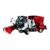
BVL V-MIX DRIVE Maximus Plus 11-1S Operating Manual (226 pages)
Self-Propelled Mixer Wagon
Brand:
BVL
| Category:
Farm Equipment
| Size: 6 MB
Table of Contents
Table of Contents
5
1 User Information
11
Purpose of the Operating Manual
11
Storing the Operating Manual
11
Locational Information in the Operating Manual
11
Illustrations Used
12
Terms Used
12
2 Safety Instructions
13
Working in a Safety-Conscious Manner
13
Organizational Measures
14
Responsibilities of the Owner
14
Responsibilities of the Operator
14
Qualification of the Personnel
15
Product Safety
16
Safe Operation of the Machine
16
Safety Devices and Guards
16
Structural Modifications
16
Replacement and Wear Parts as Well as Auxiliary Supplies
16
Warranty and Liability
17
General Safety Instructions
17
General Information on Safety and Accident Prevention
18
Hydraulic System
20
Electrical System
21
Brake System
21
Tyres
22
Mixer Wagon
23
Cleaning, Maintenance and Repairs
24
Action-Related Safety Instructions and Important Information
25
Action-Related Safety Instructions
25
Important Information
26
Warnings and Instructions
26
Warnings
27
Instructions
33
Positioning of Warnings and Instructions
36
Risks Resulting from Failure to Observe the Safety Instructions and Warnings
38
3 Loading and Unloading
39
4 Product Description
40
Overview - Entire Machine
40
Intended Use
43
Safety Devices and Guards
44
Danger Area and Hazard Areas
45
Danger Area Platform
46
Information on Noise Generation
46
Technical Data
47
Type Plate and CE Mark Type Plate and CE Mark
48
Conformity
49
5 Design and Function
50
Driver's Cab - Overview
50
Cab Door
51
Gas Pressure Spring
51
Opening the Cab Door
52
Closing the Cab Door
53
Opening the Door Window
54
Driver's Seat
55
Mechanically Cushioned Driver's Seat
56
Air-Suspended Driver's Seat (Special Equipment)
58
Steering Wheel
61
Ignition Starter Switch
61
Dashboard - Overview
62
Instruments
63
Speedometer
63
Indicator for Fuel Reserve
63
Running Time Meter
64
Indicator for Hydraulic Oil Temperature
64
Tachometer
65
Warning and Indicator Lights
66
Warning and Indicator Lights Relating to Engine Functions
66
Indicator Lights of Lighting and Turn-Signal Indicator System
67
Warning and Indicator Lights of the Traction Drive
67
Warning and Indicator Lights of the Filter Systems
67
Controls
68
Control Panel - Overview
69
Controls
69
Operating Monitor of the Diesel Engine
71
Engine Indicator Light Red
71
Engine Indicator Light Yellow
71
Warning Light Charge Check/Alternator
72
Engine Speed
72
Coolant Temperature
72
Coolant Level
73
Exhaust Aftertreatment
73
Diesel Engine Operation Monitoring by Means of Electronic Engine Control
73
Indicator and Warning Lights for the Operating States of the Hydraulic System
74
Warning Light Hydraulic Oil Temperature
74
Heating, Ventilation and Air Conditioning
74
5.1.10.1 Heating or Cooling the Cab Compartment
75
Selecting Operating Modes
77
Operating Mode "Loading
78
Operating Mode "Feeding
79
Operating Mode "Transport
80
5.1.11.4 Operating Mode "Diagnostics, Settings and Information
81
Multi-Function Lever
82
5.1.12.1 Multi-Function Lever - Mode 1: Loading
83
5.1.12.2 Multi-Function Lever - Mode 2: Feeding
84
5.1.12.3 Multi-Function Lever - Mode 3: Transport
85
Information and Operating Terminal
86
5.1.13.1 Mode 1 - Loading
87
5.1.13.2 Mode 2 - Feeding
89
5.1.13.3 Mode 3 - Transport
90
5.1.13.4 Mode 4 - Diagnostics, Settings and Information
91
5.1.13.4.1 Home Screen
91
5.1.13.4.1.1 Diagnostics
92
Status of Traction Drive
93
Inputs of Traction Drive
94
Outputs of Traction Drive
95
Machine Control
96
Status of Hydraulic Oil Filters
97
5.1.13.4.1.2 Settings
98
Time
99
Automatic Extraction Unit
100
Automatic Fan Reversal Unit
101
Language
102
Mixer Speed
103
5.1.13.4.1.3 Information
104
5.1.13.5 Error Notifications
105
5.1.13.5.1 Error Coolant
105
5.1.13.5.2 Error Notification, Cover
105
5.1.13.5.3 Error Notification, Loading Arm Position - Loading Arm too High
106
5.1.13.5.4 Error Notification, Loading Arm Position - Loading Arm too Low
107
5.1.13.5.5 Error Notification, Cross Conveyor Center Position
108
5.1.13.5.6 Error Notification, Burn-Off UREA
108
5.1.13.5.7 Error Notification, HC Burn-Off UREA, SCR Catalytic Converter
109
5.1.13.5.8 Adblue Fill Level
110
Adblue Quality Warning Level 1
111
Adblue Quality Warning Level 2
111
Adblue Quality Warning Level 3
112
Adblue Equipment Warning Level 1
112
Adblue Equipment Warning Level 2
113
Adblue Equipment Warning Level 3
114
Diesel Engine
115
Starting the Diesel Engine
115
Warming up the Diesel Engine
117
Stalling the Diesel Engine
117
Venting after Lack of Diesel Fuel
117
Starting the Diesel Engine Using a Jumper Battery
118
Tow-Starting the Diesel Engine
119
Shutting off the Diesel Engine
119
Operating the Diesel Engine in the Winter
120
Drive Mode
121
Driving Forward
122
Driving in Reverse
123
Decelerating and Stopping the Machine
124
Parking Brake (Hand Brake)
125
Switching Four-Wheel Drive on and off (Optional)
126
Differential Lock
127
Steering
128
Lighting and Visibility
129
Switching the Sidelight or Headlight on and off
129
Turn-Signal Indicator, High Beam, and Headlight Flasher
130
Hazard Warning Flasher
131
Visibility
131
Windshield Wipers
131
Mirrors
133
Rear View Camera
135
Loading Arm
136
Raising/Lowering the Loading Arm
136
Setting the Loading Arm to the Transport Position
137
Profiled Roller and Elevator
138
Switching Profiled Roller and Elevator on and off
138
Adjusting the Drive Speed of the Profiled Roller
139
Adjusting the Belt Speed of the Elevator
140
Opening/Closing the Guard on the Profiled Roller
141
Reversing Profiled Roller and Elevator
142
Opening and Closing the Dosing Gate for the Door
142
Cross Conveyor
144
Switching the Conveyor on and off
144
Adjusting the Belt Speed of the Cross Conveyor
145
Shifting the Cross Conveyor to the Right or Left (Optional)
146
Platform
147
Mixing Auger
148
Switching the Mixing Auger on and off
148
Adjusting the Drive Speed of the Mixing Auger
149
Switching Rapid Speed for the Mixing Auger on and off
150
Switching Cleaning Mode for the Mixing Auger on
151
Reverse the Drive Direction of the Mixing Auger
152
Switching the Plug Auger On/Off
152
Cutting Blades of the Mixing Auger
153
Counter Blade
154
Anti-Spill Ring
154
Weighing System
155
6 Commissioning and National Traffic Regulations
156
Traffic Regulations
156
Traffic Regulations Applicable in Germany
157
Securing the Machine against Unintended Start-Up and Rolling Away
158
Checking the Machine for Proper Operation
158
7 Use of the Machine
159
Loading the Mixer Wagon
160
Recommended Order During Filling
161
Loading Silage from a Clamp Silo
162
Loading Round Bales
164
Loading Square Bales
165
Loading Groats, Concentrated Feed, Brewer's Grains, and Other Types of Fodder Components
166
Mixing Fodder Components
167
Discharging Fodder
168
Removing Clogs
170
8 Transport Trips
171
9 Cleaning, Maintenance and Repairs
173
Cleaning
174
Lubricating
175
Lubrication Points on the Loading Arm
176
Lubrication Points on the Rear Cross Conveyor
177
Lubrication Points on the Side Elevator
178
Lubrication Points on the Front and Rear Axles
179
Other Lubrication Points on the Machine
180
Maintenance Schedule
181
Checking and Refilling
181
Refueling
182
Adblue
183
Adblue Fill Level
183
Topping off Adblue
184
Working in the Engine Compartment
185
Opening the Engine Compartment Cover
186
Closing the Engine Compartment Cover
187
Opening the Assembly Hatch
188
Closing the Assembly Hatch
188
Diesel Engine Oil
189
Checking the Engine Oil Level
190
Refilling Engine Oil
191
Changing Engine Oil and Filters
192
Coolant
193
Checking the Coolant Level
193
Refilling Coolant
194
Hydraulic Oil
195
Check Hydraulic Oil Level
196
Refilling Hydraulic Oil
197
Changing the Hydraulic Oil
198
Changing the Filter Elements
200
Central Lubrication System (Optional)
202
Checking the Lubricant Level
202
Topping off Lubricant
202
Fan Reversal Unit (Optional)
203
Windshield Washer Fluid and Windshield Wiper Blades
203
Refilling Windshield Wiper Fluid
203
Changing the Windshield Wiper Blades
204
Air Filter
205
Fresh Air Filter
206
Attaching/Removing the Support for the Loading Arm
207
Profiled Roller
207
Resharpening Profiled Roller Segments
208
Replacing Profiled Roller Segments
209
Entering the Mixing Hopper
210
Installation and Positioning of the Mixing Augers
212
Cutting Blades of the Mixing Auger
213
Sharpening Cutting Blades
213
Swiveling/Replacing Cutting Blades
214
Conveyor Belt
215
Belt Connection
215
Tensioning/Aligning the Conveyor Belt
216
Releasing the Parking Brake Manually
217
Towing the Machine
218
Selecting Operating Modes with Defective Sensor in Emergency Mode
219
Activating Emergency Mode
219
Switching on the Profiled Roller
219
Tyres
219
Changing the Tyres
220
Hydraulic System
222
Markings on Hydraulic Hose Lines
222
Maintenance Intervals
223
Criteria for Inspections of Hydraulic Hose Lines
223
Advertisement
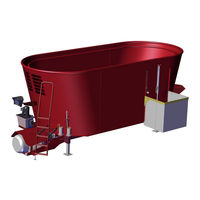
BVL V-MIX DRIVE Maximus Plus 11-1S Operating Manual (205 pages)
Brand:
BVL
| Category:
Farm Equipment
| Size: 11 MB
Table of Contents
Table of Contents
4
User Instructions
9
Purpose of the Operating Manual
9
Storing the Operating Manual
9
Locations Referenced in the Operating Manual
9
Depictions Employed
10
Terms Used
10
Safety Information
11
Safety-Conscious Work
11
Organizational Measures
12
Obligations of the Owner
12
Obligations of the Operator
13
Personal Qualifications
14
Product Safety
15
Safe Operation of the Machine
15
Safety and Protective Equipment
15
Structural Modifications
15
Replacement and Wear Parts as Well as Auxiliary Materials
16
Guarantee and Liability
17
General Safety Instructions
18
General Information on Safety and Accident Prevention
18
Attaching and Uncoupling the Machine
18
Use of the Machine
19
Driving to Transport the Machine
21
Hydraulic System
23
Electrical System
24
PTO Shaft Operation
25
Attached Machines
26
Braking System
26
Tires
28
Feed Mixer Wagon
29
Cleaning, Maintenance and Servicing
30
Handling-Related Safety Instructions and Important Information
31
Handling-Related Safety Instructions
31
Important Information
32
Warning Alerts and Instructional Notices
33
Warning Notices
33
Instructional Notices
42
Placement of Warning Alerts and Instructional Notices
47
Placement of Warning Alerts and Instructional Notices (Canada / U.S. Only)
48
Risk Associated with Failure to Follow Safety Instructions and Warning Alerts
50
Loading and Unloading
51
Product Description
52
Assemblies - Overview
53
Safety and Protective Equipment
55
Supply Lines between Tractor and Machine
56
Technical Equipment for Roadway Traffic
56
Intended Use
57
Hazard Area and Dangerous Sites
58
Model Plate and EC Marking
59
Technical Data
60
V-MIX Agilo
60
V-MIX Plus
62
V-MIX Plus 2S
64
V-MIX Plus 3S
66
V-MIX Giant 40 - 46 3S
68
Information Regarding Noise Production
70
Compliance
70
Required Tractor Equipment
71
Construction and Function
73
Mixing Tank and Mixing Auger
73
Vario Volumen
74
Gearbox
75
Cutting Blades
76
Overflow Ring
77
Counter-Blades
78
Loading Hopper for Mineral and Concentrated Feed
79
Loading Tube for Molasses
79
Work Platform and Viewing Window
80
Delivery Variations
81
Possible Arrangement of Delivery Openings
81
Open and Close Dosing Valve for Discharge Opening
83
4.3.1.2 Delivery Slide for Lateral Delivery Openings
84
Transverse Conveyor Belt
85
Lateral Conveyor
86
Set Conveyor Belt Speed
87
Setting the Belt Speed by Hand (Optional)
87
Setting the Belt Speed by Control Panel (Optional)
87
Straw Blower
88
Weighing Scale
89
Align Scale Display
89
5.6 Camera System / Monitor - Optional Equipment
90
Control Panel
91
Switching the Control Panel on and off
92
Set Conveyor Belt Speed
92
Open / Close the Delivery Opening
93
Activate Conveyor Belt
93
Switch On/Off Working Headlights
94
Raise/Lower Support Leg
94
Swing Counter-Blades in / out
94
Swing the Straw Blower in / out
95
Swing the Discharge Hood/Tower in / out
95
Fold/Unfold Feed Slide
96
Vario - Volumen Input/Delivery
96
Gearbox High/Low Speed
96
Towbar
97
Clevis Connection
97
Hitch-Type Connection
98
Couple the Towbar
99
Bolt Coupler
100
Coupling Hook (Hitch Hook) and Towbar Eye (Hitch Ring)
101
Coupling Piton (Piton Fix) and Towbar Eye (Hitch Ring)
101
K80 Ball Coupler with K80 Towbar Eye
102
Coupling with Clevis Towbar Eye (for Canada and the U.S.)
103
Uncouple the Towbar
104
Bolt Coupler
104
Coupling Hook (Hitch Hook) and Towbar Eye (Hitch Ring)
105
Coupling Piton (Piton Fix) and Towbar Eye (Hitch Ring)
105
K80 Ball Coupler with K80 Towbar Eye
106
Coupling with Clevis Towbar Eye (for Canada and the U.S.)
106
Support Leg
107
Raise Hydraulic Support Leg into Transport Position
108
Lower Hydraulic Support Leg into Support Position
108
PTO Shaft
109
Coupling the Drive Shaft
111
Uncoupling the Drive Shaft
112
Hydraulic System
113
Via the Control Panel
114
Electrohydraulic Control Block
114
Emergency Manual Activation in the Event of Power Failure
114
Electromagnetic Flow Regulator Valve
114
Hydraulic Hoses
115
Attach the Hydraulic Hoses
115
Detach the Hydraulic Hoses
116
Technical Equipment for Roadway Traffic
117
Braking System
118
Hydraulic Service Brake
118
Coupling
119
Decoupling
120
Hydraulic Service Brake (EU Version)
121
Coupling
122
Decoupling
122
Two-Line Service Brake System
123
Couple the Brake Line and Reservoir Lines
125
Uncouple the Brake Line and Reservoir Line
126
Use a Shunting Vehicle to Shunt the Uncoupled Machine
127
The Introductory Service Brake System (Not Permitted in Germany, Solely for Export)
128
Couple the Reservoir Lines
130
Uncouple the Supply Tubes
130
Use a Shunting Vehicle to Shunt the Uncoupled Machine
131
Parking Brake
132
Startup
133
Provisions of Traffic Law
134
Traffic Regulations for Germany
134
Tips on Traffic Regulations for Canada/The U.S
135
Check the Tractor's Suitability
135
Calculation of Actual Values
137
Required Data
137
Tractor's Minimum Ballast
138
Actual Tractor Front Axle Load
138
Actual Total Weight of the Tractor-Machine Combination
138
Actual Tractor Rear Axle Load
138
The Capacity of the Tires Mounted on the Tractor
138
Table
139
Requirements for Operating Tractors with Attached Machines
140
Combined Connection-Towing Device Options
140
C Values Based on the Combination to be Coupled141
141
Secure the Tractor and the Machine to Prevent Unintentional Startup and Rolling
142
Adjust the Towbar's Attachment Height (Workshop Task)
144
Adjust the Drive Shaft Length to the Tractor (Workshop Task)
146
Mount the Control Panel Onto the Tractor
148
Check the Functioning of the Machine
149
Getting Started
150
Coupling and Uncoupling the Machine
151
Couple the Machine
151
Uncouple the Machine
153
Settings
154
Use of the Machine
155
Loading the Feed Mixing Wagon
156
Recommended Filling Sequence
158
Vario Volumen
159
Mixing
160
Feed Delivery
161
Delivery Openings
162
Fiber Door" Delivery Opening - Optional Equipment
162
Transverse Conveyor Belt
163
Lateral Conveyor
164
Resolving Blockages
165
Transport Drives
166
Cleaning, Maintenance and Servicing
168
Cleaning
169
Lubrication
170
Overview of the Lubrication Plan
170
Overview - Lubrication Points - V-MIX 6.5 - 18 1S
171
Overview - Lubrication Points - V-MIX 13 2S - 46 3S
172
K80 Ball Coupler Lubrication - (K80 Towbar Eye Option)
173
Oil Change for Planetary Drive and Gearbox
173
Bvl Transmission 0100734 ECS 1522
174
Bvl Transmission 0094102 ECS 1202
175
Bvl Transmission 0094389 ECS 1602
176
Bvl Transmission 0095277 ECS 2502
177
Bvl 94954, 94955 and 108143 Reduction Gear (Optional Equipment)
178
Switchable Reduction Gear (Optional Equipment)
179
Powershift Transmission (Optional Equipment)
179
Maintenance Plan - Overview
179
Replace the Shear Bolt in the Shear Bolt Coupling
179
Entry into the Mixing Chamber
180
Installation and Positioning of the Mixing Augers
182
Mixing Auger Cutting Blades
183
Sharpen Cutting Blades
183
Turn/Replace the Cutting Blades
184
Conveyor Belt
185
Belt Connection
185
Tensing/Guiding the Conveyor Belt
185
Towbar Eye
186
Tires
186
11.11.1 Replace Tires
187
Hydraulic System
189
11.12.1 Hydraulic Hose Markings
190
11.12.2 Maintenance Interval
190
11.12.3 Inspection Criteria for Hydraulic Hose Connections
191
11.12.4 Installation and Removal of Hydraulic Hoses
192
Tightening Torques for Flange Connections
193
Malfunctions
194
Circuit Diagrams
196
Hydraulic Circuit Diagram - for 4 Functions Operated Via the Control Panel
196
Electrical Diagram
197
Important Information
198
Prior to First-Time Use of
198
Check the Tractor's Suitability
198
Calculation of Actual Values
199
14.2.1 Required Data
199
14.2.2 Tractor's Minimum Ballast
200
14.2.3 Actual Tractor Front Axle Load
200
14.2.4 Actual Total Weight of the Tractor-Machine Combination
200
14.2.5 Actual Tractor Rear Axle Load
200
14.2.6 the Capacity of the Tires Mounted on the Tractor
200
14.2.7 Determination of Forward Weight
201
Requirements for Operating Tractors with Attached Machines
202
14.3.1 Combined Connection-Towing Device Options
202
Calculate the Actual D Values Based on the Combination to be Coupled
203
Note
204
EC Declaration of Conformity
205
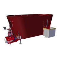
BVL V-MIX DRIVE Maximus Plus 11-1S Operating Manual (214 pages)
Self-Propelled Feeder Wagon
Brand:
BVL
| Category:
Farm Equipment
| Size: 3 MB
Table of Contents
Table of Contents
5
1 User Information
10
Purpose of this Operating Manual
10
Storing the Operating Manual
10
Locational Information in this Operating Manual
10
Illustrations Used
11
Terms Used
11
2 Safety Instructions
12
Working in a Safety-Conscious Manner
12
Organizational Measures
13
Responsibilities of the Owner
13
Responsibilities of the Operator
13
Qualification of the Personnel
14
Product Safety
15
Safe Operation of the Machine
15
Safety Devices and Guards
15
Structural Modifications
15
Replacement and Wear Parts as Well as Auxiliary Supplies
15
Warranty and Liability
16
General Safety Instructions
16
General Information on Safety and Accident Prevention
16
Hydraulic System
18
Electrical System
19
Brake System
19
Tires
20
Feeder Wagon
21
Cleaning, Maintenance and Repairs
22
Action-Related Safety Instructions and Important Information
23
Action-Related Safety Instructions
23
Important Information
24
Warnings and Instructions
24
Warnings
24
Instructions
31
Positioning of Warnings and Instructions
32
Risks Resulting from Failure to Observe the Safety Instructions and Warnings
34
3 Loading and Unloading
35
4 Product Description
36
Overview - Entire Machine
36
Intended Use
38
Safety Devices and Guards
39
Danger Area and Hazard Areas
40
Information on Noise Generation
40
Technical Data
41
Type Plate and CE Mark Type Plate and CE Mark
46
Conformity
47
5 Design and Function
48
Driver's Cab - Overview
48
Cab Door
49
Gas Pressure Spring
49
Opening the Cab Door
50
Closing the Cab Door
51
Opening the Door Window
51
Emergency Exit
52
Driver's Seat
53
Mechanically Cushioned Driver's Seat
54
Air-Suspended Driver's Seat (Special Equipment)
56
Steering Wheel
59
Ignition Starter Switch
59
Dashboard - Overview
60
Instruments
60
Speedometer
60
Tachometer
61
Time
61
Running Time Meter
61
Indicator for Hydraulic Oil Temperature
62
Indicator for Fuel Reserve
62
Warning and Indicator Lights
63
Warning and Indicator Lights Relating to Engine Functions
63
Indicator Lights of Lighting and Turn-Signal Indicator System
64
Warning and Indicator Lights of the Traction Drive
64
Warning and Indicator Lights of the Filter Systems
65
Controls
65
Control Panel - Overview
66
Controls
66
Operating Monitor of the Diesel Engine
69
Warning Light Charge Check/Alternator
69
Engine Speed
69
Coolant Temperature
70
Diesel Engine Operation Monitoring by Means of Electronic Engine Control
71
Using the Diagnostic Button
71
Indicator and Warning Lights for the Operating States of the Hydraulic System
72
Warning Light Hydraulic Oil Temperature
72
Heating, Ventilation and Air Conditioning
72
Heating or Cooling the Cab Compartment
73
Selecting Operating Modes
75
Operating Mode "Loading
76
Operating Mode "Feeding
77
Operating Mode "Transport
78
Operating Mode "Diagnostics and Settings
79
Multi-Function Lever
80
Multi-Function Lever - Mode1: Loading
81
Multi-Function Lever - Mode2: Feeding
82
Multi-Function Lever - Mode3: Transport
83
Display
84
All Modes
85
Error Coolant
85
Error Oil Pressure
86
Mode 1 - Loading
87
Home Screen
87
Mixing Auger
89
Feeding Auger
90
Error Cover
91
Mode 2 - Feeding
92
Advertisement
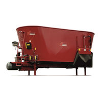
BVL V-MIX DRIVE Maximus Plus 11-1S Operating Manual (103 pages)
Brand:
BVL
| Category:
Farm Equipment
| Size: 5 MB
Table of Contents
Table of Contents
5
1 User Instructions
8
Purpose of the Operating Manual
8
Storage of the Operating Manual
8
Locations Referenced in the Operating Manual
9
Depictions Employed
10
Terms Used
10
2 Safety Information
11
Safety-Conscious Work
11
Organizational Measures
11
Obligations of the Owner
12
Obligations of the Operator
12
Personal Qualifications
13
Intended Use
14
Reasonably Foreseeable Misuse
14
Product Safety
15
Safe Operation of the Machine
15
Safety and Protective Equipment
15
Structural Modifications
15
Replacement and Wear Parts as Well as Auxiliary Materials
16
Guarantee and Liability
16
General Safety Instructions
17
General Information on Safety and Accident Prevention
17
Use of the Machine
17
Hydraulic System
18
Electrical System
18
Cleaning, Maintenance and Servicing
19
Handling-Related Safety Instructions and Important Information
19
Handling-Related Safety Instructions
20
Important Information
21
Warning Alerts and Instructional Notices
21
Warning Notices
22
Instructional Notices
26
Placement of the Warning Alerts and Instructional Notices
28
Risk Associated with Failure to Follow Safety Instructions and Warning Alerts
31
3 Technical Data
32
V-MIX Fix Plus 6.5-1S To14-1S
32
V-MIX Fix Plus 13-2S to 30H2S
33
Model Plate and EC Marking
35
Hydraulic Aggregate
35
Load Capacity Limits
35
Operating Materials
36
Information Regarding Noise Production
36
4 Construction and Function
37
Overview V-MIX Fix Plus
37
V-MIX Fix Plus - Assemblies Overview
38
Mixing Chamber
38
Access Ladder and Viewing Panel
39
Overflow Ring
39
Mixing and Dosing Apparatus
40
Mixing Auger with Cutting Blades
41
Delivery Area (Delivery Opening)
42
Conveyor Belt (Optional)
43
Cross Conveyor Belt (Optional)
43
Counter-Blades
44
Weighing Scales (Optional)
45
Hydraulic Aggregate (Optional)
45
Hydraulic Aggregate 5.5 KW
45
Hydraulic Aggregate 1.1 KW
46
Electrohydraulic Control Block
46
Hydraulic Hand Pump (Optional)
46
Oil Cooler (Optional)
47
Control Cabinet (Optional)
48
Basic" Control
48
Control Cabinet "Basic" Control Overview
48
Main Switch/Emergency Stop/Off Button "Basic" Control
49
Switching on the "Basic" Control System
49
Confirming Error Messages
49
Operating the "Basic" Control System
50
Service - Error Message Readouts in "Basic" Control
51
Plus" Control
52
Control Cabinet "Plus" Control Overview
52
Main Switch/Emergency Stop/Off Button "Plus" Control
53
Switching on the "Plus" Control System
53
Confirming Error Messages
53
Plus" Control Manual Operation
54
Plus" Control Automatic Operation
55
Plus" Control Automatic Operation Start Screen
55
6.1.2Setting Runtime in „Plus" Control Automatic Operation
55
6.1.3Error Messages in "Plus" Control
56
6.1.4"Plus" Control Maintenance Overview
56
6.1.5"Plus" Control Bvl Service Menu (Password Protected)
58
Basic" and "Plus" Remote Control (Optional)
60
Remote Control Functions
61
Linking Switches and Buttons to the Transmitter
61
Meaning of the Transmitter Leds
62
Power On/Activate Transmitter
62
Remote Control Use
63
Remote Control off
63
Transmitter Button Lock
63
Transmitter Battery Change
64
Safety and Protective Equipment
65
Cover Aprons
65
Block Ball Valve
66
Main Drive Shaft Protective Panels
66
Emergency Stop Button
66
5 Transport, Setup and Initial Startup
67
Scope of Delivery
67
Loading and Unloading the Machine with Load Hoists
68
Installing the Machine
68
Electrical Connection
69
Check the Functioning of the Machine
70
6 Operation and Control
71
Switching on the Machine
71
Powering up Following Emergency Stop or Malfunction
71
Beginning and Concluding the Mixing Process
72
Load the Mixing Chamber
72
Recommended Filling Sequence
73
Output Feed
74
Resolving Blockages
76
7 Cleaning, Maintenance and Servicing
77
Cleaning
78
Lubrication
78
Lubricating Points
79
Maintenance Plan - Overview
80
Replace Transmission Oil
81
Brevini ECS1512 Transmission
82
Brevini EM1065 Transmission
83
Comer PGA1602 Transmission
84
Bvl 108960 Reduction Gear (Optional Equipment)
85
Entry into the Mixing Chamber
86
Delivery Opening with Protruding Cover Apron
87
Delivery Opening with Closely-Fitting Cover Apron (Optional)
88
Delivery Opening with Closely-Fitting Cover Apron and Conveyor Belt (Optional)
89
Installation and Positioning of the Mixing Augers
89
Mixing Auger Cutting Blades
90
Sharpen Cutting Blades
90
Turn/Replace the Cutting Blades
91
Hydraulic System
92
Hydraulic Aggregate 5.5 KW (Optional)
93
Hydraulic Aggregate 5.5 KW Maintenance Plan
93
Monitor the Oil Level of Hydraulic Aggregate 5.5 KW
93
Replenish Hydraulic Oil Hydraulic Aggregate 5.5 KW
94
Hydraulic Aggregate 5.5 KW Oil Change
94
Hydraulic Aggregate 1.1 KW (Optional)
95
Hydraulic Aggregate 1.1 KW Maintenance Plan
95
Monitor the Level of Hydraulic Oil Hydraulic Aggregate 1.1 KW
95
Replenish Hydraulic Oil Hydraulic Aggregate 1.1 KW
96
Hydraulic Aggregate 1.1 KW Oil Change
96
Hydraulic Hand Pump (Optional)
97
Check the Oil Level of the Hydraulic Hand Pump, Refill and Replace the Oil
97
Hydraulic Hose Markings
98
Maintenance Interval
98
Inspection Criteria for Hydraulic Hose Connections
98
Installation and Removal of Hydraulic Hoses
99
Conveyor Belt (Optional)
99
Belt Connection
100
Tensing/Guiding the Conveyor Belt
100
Tightening Torques for Flange Connections
101
8 Malfunctions
102
9 Appendix
103
Documentation Supplied by Third-Party Producers
103
Circuit Diagrams
103
BVL V-MIX DRIVE Maximus Plus 11-1S Operating Manual (92 pages)
Brand:
BVL
| Category:
Farm Equipment
| Size: 1 MB
Table of Contents
Table of Contents
5
User Information
7
Purpose of this Operating Manual
7
Storing the Operating Manual
7
Locational Information in this Operating Manual
7
Illustrations Used
8
Terms Used
9
Safety Instructions
10
Working in a Safety-Conscious Manner
10
Organizational Measures
10
Responsibilities of the Owner
11
Responsibilities of the Operator
11
Qualification of the Personnel
12
Intended Use
13
Reasonably Foreseeable Misuse
13
Product Safety
14
Safe Operation of the Machine
14
Safety Devices and Guards
14
Structural Modifications
14
Replacement and Wear Parts as Well as Auxiliary Supplies
15
Warranty and Liability
15
General Safety Instructions
16
General Information on Safety and Accident Prevention
16
Use of the Machine
16
Hydraulic System
17
Electrical System
17
Cleaning, Maintenance and Repairs
18
Action-Related Safety Instructions and Important Information
19
Action-Related Safety Instructions
19
Important Information
20
Warnings and Instructions
20
Warnings
21
Instructions
25
Positioning of Warnings and Instructions
27
Risks Resulting from Failure to Observe the Safety Instructions and Warnings
31
Technical Data
32
V-MIX Fix Plus 6.5-1S to 15-1S
32
V-MIX Fix Plus 13-2S to 25-2S
33
Type Plate and CE Mark
35
Hydraulic Unit
35
Capacity Limits
36
Operating Fluids
36
Information on Noise Generation
36
Design and Function
37
Overview of the V-MIX Fix Plus
37
V-MIX Fix Plus - Overview of Assemblies
38
Mixing Hopper
39
Ladder and Inspection Window
39
Anti-Spill Ring
40
Mixing and Dispenser Unit
41
Mixing Auger with Cutting Blades
42
Discharge Area (Discharge Opening)
43
Conveyor Belt (Optional)
44
Cross Conveyor (Optional)
44
Counter Blades
45
Weighing System (Optional)
46
Hydraulic Unit (Optional)
47
Electrohydraulic Control Block
47
Hydraulic Hand Pump (Optional)
48
Oilcooling
49
Control Switch Cabinet
50
Main Switch
51
Emergency Stop Button
51
Operating Elements and Controls
52
Display
53
Safety Devices and Guards
55
Cover Aprons
55
Block Ball Valve
56
Motor and Main Drive Shaft Protective Plates
56
Emergency Stop Button
56
Transport, Setup, and Initial Commissioning
57
Scope of Delivery as Supplied
57
Loading and Unloading the Machine Using Lifting Devices
58
Machine Setup
59
Connecting the Electrical System
61
Checking the Machine for Proper Operation
61
Use and Operation
62
Switching the Machine on
62
Switching on after Emergency Stop or Fault
62
Starting and Ending the Mixing Process
63
Filling the Mixing Hopper
64
Recommended Order During Filling
65
Discharging Fodder
66
Removing Clogs
68
Starting and Ending Cleaning Mode
69
Cleaning, Maintenance and Repairs
70
Cleaning
71
Lubricating
71
Lubrication Points
72
Maintenance Schedule - Overview
73
Oil Change at the Gear Unit
74
Gear Unit Brevini ECS1512
75
Gear Unit Brevini EM1065
76
Gear Unit Comer PGA1602
77
Reduction Gearbox Bvl 108960 (Special Equipment)
78
Entering the Mixing Hopper
79
Discharge Opening with Protruding Cover Apron
80
Discharge Opening with Tight-Fitting Cover Apron (Optional)
81
Discharge Opening with Tight-Fitting Cover Apron and Conveyor Belt (Optional)
82
Installation and Positioning of the Mixing Augers
82
Cutting Blades of the Mixing Auger
83
Sharpening Cutting Blades
83
Swiveling/Replacing Cutting Blades
84
Hydraulic System
85
Checking the Hydraulic Oil Level
86
Refilling Hydraulic Oil
86
Markings on Hydraulic Hose Lines
87
Maintenance Intervals
87
Inspection Points for Hydraulic Hose Lines
87
Installing and Removing Hydraulic Hose Lines
88
Conveyor Belt (Optional)
89
Belt Connection
89
Tensioning/Aligning the Conveyor Belt
89
Tightening Torques for Bolt Joints
90
Faults
91
Appendix
92
Supplied Third-Party Documents
92
Circuit Diagrams
92
BVL V-MIX DRIVE Maximus Plus 11-1S Operating Manual (90 pages)
Brand:
BVL
| Category:
Farm Equipment
| Size: 1 MB
Advertisement
Related Products
BVL V-MIX DRIVE Maximus Plus 15-1S
BVL V-MIX DRIVE Maximus Plus 17-1S
BVL V-MIX Fix Plus 10H-1S
BVL V-MIX Fix Plus 10N-1S
BVL V-MIX Fix Plus 13-2S
BVL V-MIX Fix Plus 15-2S
BVL V-MIX Fix Plus 15N-2S
BVL V-MIX Fix Plus 17N-2S
BVL MIXDRIVE Maximus Plus 1S
BVL V-MIX Plus 18 2S
BVL Categories
Farm Equipment
Cutter
More BVL Manuals
Login
Sign In
OR
Sign in with Facebook
Sign in with Google
Upload manual
Upload from disk
Upload from URL