Table of Contents
Advertisement
Available languages
Available languages
Quick Links
Advertisement
Table of Contents

Related Manuals for Nice WM100


Summary of Contents for Nice WM100
- Page 1 WM100 Module pour connecter le accessoires sans fil FR - Instructions et avertissements pour l’installation et l’utilisation EN - Instructions and warnings for installation and use IT - Istruzioni ed avvertenze per l’installazione e l’uso PL - Instrukcje i ostrzeżenia do instalacji i użytkowania...
- Page 2 WM100 FLW200 PHW200 PHW200 FLW200 WM100...
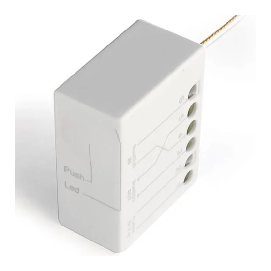
- Page 3 Beep PHW200 FLW200 led “C” led “D” led “A” led “B” led “E” jumper “J” button “T” jumper “J”...
- Page 5 RECOMMANDATIONS GÉNÉRALES : SÉCURITÉ - INSTALLATION - UTILISATION ATTENTION Instructions importantes pour la sécurité. Il est important de suivre toutes les instructions fournies étant donné qu’u- ne installation incorrecte est susceptible de provoquer des dommages graves ATTENTION Instructions importantes pour la sécurité. Pour la sécurité des personnes, il est important de suivre ces instructions.
-
Page 6: Description Du Produit Et Application
WM100 est une interface radio avec la technologie Power&Free System de la gamme Nice Home. Elle s’interface via radio avec les dispositifs sans fil de la gamme Nice Home (fig. 1) : photocellule PHW200 et clignotant FLW200. Elle ne peut être connectée via un câble qu’à une logique de commande de la gamme Nice Home compatible avec la communication « ECSbus ». -
Page 7: Installation
INSTALLATION 3.1 - VÉRIFICATIONS PRÉLIMINAIRES Seule, l’interface WM100 n’est pas un système de connexion sans fils com plet mai seulement un élément de celui-ci. Par conséquent, pour pouvoir l’utiliser, il faut l’associer à au moins l’un des accessoires sans fil mentionné au chapitre 2. -
Page 8: Caractéristiques Techniques
3.3 - CARACTÉRISTIQUES TECHNIQUES Dans le but d’améliorer ses produits, NICE S.p.A. se réserve le droit d’en modifier à tout moment et sans préavis les caractéristiques techniques, en garantissant dans tous les cas le bon fonctionnement et le type d’utilisation prévus. Toutes les caractéristiques techniques se réfèrent à la température de 20 °C. - Page 9 03. En se référant aux manuels respectifs de PHW200 et FLW200, insérer les cavaliers afin d’obtenir le réglage désiré. 04. Accéder à la centrale de l’automatisme et brancher l’interface WM100 à la centrale (voir le chapitre 4). 05. Rapprocher tous les dispositifs wireless de l’interface WM100 et effectuer la programmation de chacun d’eux (voir le chapitre 5, et identifier le paragraphe...
-
Page 10: Raccordements Électriques
08. Au terme du test fixer de manière définitive chaque élément sans fil aux endroits prévus (voir les figures 7, 8, 9). Fixer l’interface WM100 à proximité de la centrale ou à l’intérieur de celle-ci, en la protégeant de manière adéquate (fig 2). - Page 11 TX et RX prévues dans l’installation, sans distinction entre les photocellules sans fil et celles câblées. PROGRAMMATION Pour que WM100 et les dispositifs sans fils puissent communiquer entre eux via radio, il faut lancer la phase « d’acquisition ». Avertissements pour la programmation : •...
- Page 12 Remarque - Les photocellules PHW200 se remettent à zéro automatiquement, Il n’est donc pas nécessaire d’effectuer une procédure d’annulation. 03. Maintenir enfoncée la touche de WM100 (fig. 3) et la relâcher jusqu’à ce que la led s’allume en vert fixe : l’interface est désormais prête à reconnaître les dispositifs sans fil.
- Page 13 à la configuration usine par le biais de la procédure décrite dans le paragraphe 5.5 01. Maintenir enfoncée la touche de WM100 (fig. 3) et la relâcher une fois la led verte allumée. La led commencera à clignoter rapidement et WM100 tentera de communiquer avec chacun des dispositifs préexistants dans l’installation...
- Page 14 01. Maintenir enfoncée la touche de WM100 (fig. 3) pendant 10 secondes environ et la relâcher une fois la led rouge allumée. 02. Enfoncer de nouveau et relâcher la touche de WM100 (fig. 3) : au bout de 5 secondes, la led rouge commence à clignoter, indiquant que la phase d’effa- cement a été...
- Page 15 01. Activer la modalité « vérification du fonctionnement » de l’installation : a) - après avoir créé l’installation, enfoncer et relâcher la touche de WM100 (fig. 3) : cette opération active la modalité « vérification du fonctionnement » de l’installation. Une manœuvre de l’automatisme sans en activer les composants mécaniques est simulée dans cette phase ;...
- Page 16 : rapprocher le plus possible le dispositif sans fil de l’antenne de WM100, ou déplacer l’antenne dans une position plus élevée du sol et/ou l’éloigner d’éventuels éléments métalliques. Ensuite, partir du point 02 jusqu’à...
- Page 17 7.1.1 - Branchement de WM100 ad une centrale générique de Nice Home, avec l’utilisation du dispositif de signalisation clignotant FLW200 Si WM100 n’a acquis aucun dispositif sans fils elle émettra un clignotement rouge toutes les secondes, sinon, elle émettra des clignotements comme indiqué dans les paragraphes 7.1.1.
- Page 18 (batterie déchargée ou mauvais signal de l’un des dispositifs), WM100 (fig. 3) émettra un son de type bip-bip. 7.1.2- Signalements au cours d’une manœuvre/essai Au cours de la manœuvre (ou de la phase de vérification de l’installation), la led verte clignote en permanence et par intermittence.
- Page 19 « vérification du fonctionnement ». 02. Effectuer les vérifications mentionnées dans les points successifs. 03. A la fin, appuyer et relâcher la touche de WM100 (fig. 3) pour sortir de la moda- lité « vérification du fonctionnement » ou attendre 2 minutes.
-
Page 20: Maintenance
– S’assurer que la logique de commande a reconnu tous les dispositifs présents dans l’interface WM100 : si la logique de commande ne les a pas reconnu, WM100 signale l’état par un son périodique (bip) émis pendant la manœuvre ou pendant la procédure de vérification du fonctionnement. -
Page 21: Remplacement Des Batteries
propreté des surfaces des cellules solaires pour garantir l’efficience maximale de la recharge. Les dispositifs ont été étudiés pour fonctionner au moins 10 ans dans des conditions normales. Au delà de cette période, il est opportun d’augmenter la fréquence des interventions d’entretien. 8.3 - REMPLACEMENT DES BATTERIES Pour le remplacement des piles dans les différents dispositifs, voir la notice corre- spondante et les recommandations suivantes :... -
Page 22: Mise Au Rebut
MISE AU REBUT Ce produit fait partie intégrante de l’automatisme et doit donc être mis au rebut avec cette dernière. Tout comme l’installation, les opérations de démantèlement, à la fin de la durée de vie de ce produit, doivent être effectuées par du personnel qualifié. Ce produit se compose de divers matériaux : certains peuvent être recyclés, d’au- tres doivent être mis au rebut. -
Page 23: General Warnings: Safety - Installation - Use
GENERAL WARNINGS: SAFETY - INSTALLATION - USE CAUTION Important safety instructions. Observe all the instructions as improper installation may cause serious damage CAUTION Important safety instructions. It is important to comply with these instructions to ensure personal safety. Store these in- structions •... -
Page 24: Product Description And Intended Use
It communicates via radio with wireless devices from the Nice Home range (fig. 1): PHW200 photocell and FLW200 flashing light. It can only have hardwire connection to a control unit from the Nice Home range that is compatible with “ECSbus” communication. -
Page 25: Installazione Installation
WM100 can only be installed in spaces that are protected against water, moisture and dust. It can only be connected to a control unit from the Nice Home range that is com- patible with “ECSbus” communication. The maximum number of accessories that can be connected to a control unit depends on the technical characteristics of the “ECSbus”... -
Page 26: Technical Characteristics
3.3 - TECHNICAL CHARACTERISTICS In order to improve its products, NICE S.p.A. reserves the right to modify their technical specifications at any time and without prior notice. In any case, the manufacturer guarantees their functionality and fitness for the intended purposes. All the technical specifications refer to a temperature of 20°C. - Page 27 04. Access the automation control unit (see the instructions manual) and connect the WM100 interface to the control unit (see chapter 4). 05. Put all wireless devices close to the WM100 interface to program each one (refer to chapter 5 and find the section for the purpose you require).
-
Page 28: Electrical Connections
08. After the inspection, fix each single wireless device to the preestablished points (refer to figs. 7, 8, 9). Fix the WM100 interface in proximity to the control unit or inside it and protect it adequately (fig. 10). Finally, use the double stick tape included in the supply to fasten the antenna in the position established during the inspection. - Page 29 TX and RX pairs included in the system, but without distinguishing between the wireless and hardwired photocells. PROGRAMMING You need to run the “acquisition” phase to enable the WM100 and the wireless devices to communicate with each other via radio. Warnings for programming: •...
- Page 30 Note - The PHW200 photocells are self-resetting, so do not require any deletion procedure. 03. Press and hold the WM100 button (fig. 3) and release it once the led is lit with a continuous green light: now, the interface unit is ready to acquire wireless devices.
- Page 31 5.4.2 so the device can no longer communicate. 02. Press and hold the WM100 button (fig. 3) and release it after the green led comes on. When released, the led will begin to flash rapidly and WM100 will try to communicate with each of the devices already on the system and these will go into programming status.
- Page 32 5.4.1 - Deleting an WM100 01. Press and hold the WM100 button (fig. 3) for about 10 seconds and release it after the red led comes on. 02. Press and release the WM100 button again (fig. 3): after 5 seconds the red led will start flashing, indicating that the deletion phase has been activated.
- Page 33 01. Activating the system’s “operation check” procedure: a) - after creating the system, press and release the WM100 button (fig. 3): this operation enables the system’s “operation check”; in this phase a manoeuvre is simulated without actually activating the mechanical components;...
- Page 34 WM100 aerial or move the aerial to a higher position above ground and/or move it away from any metal parts. Then, proceed from point 02 until good performance is achieved.
-
Page 35: System Diagnostics
SYSTEM DIAGNOSTICS 7.1 - WM100 SIGNALS If the WM100 has no wireless device acquired, it will flash red once per second; otherwise it will flash as described under sections 7.1.1 and 7.1.2. 7.1.1 - Signals with control unit on stand-by... - Page 36 The red led, conversely, indicates that a dangerous situation or system malfunction has been detected. 7.2 - FLW200 SIGNALS 7.2.1 - Signaling with control unit on stand-by When the control unit is stopped (not maneuvering), and you remove the battery from the device in question and put it back, the device will execute the following signals: Flashes...
- Page 37 • Searching for a radio interface: when the battery is inserted, the device searches for the WM100 it was linked to, or for a new one in programming mode. • Programming: if a new WM100 interface is found that is listening for new devices, it enters programming mode;...
- Page 38 • The automation does not stop and does not reverse the maneuver when a safety device intervenes. – Make sure that the control unit has acquired all the devices on the WM100 interface: if the control unit has not acquired them, the WM100 signals this sta- tus with a periodic beep emitted during the manoeuvre or during the “operation...
-
Page 39: Replacing The Batteries
8.3 - REPLACING THE BATTERIES To replace the batteries in the various devices, see their respective instruction manuals and follow these warnings: • before starting the work, make sure the automation is stopped; • insert the new batteries making sure the polarity is correct; •... -
Page 41: Avvertenze Generali: Sicurezza - Installazione - Uso
AVVERTENZE GENERALI: SICUREZZA - INSTALLAZIONE - USO ATTENZIONE Istruzioni importanti per la sicurezza. Seguire tutte le istruzioni poiché l’installazione non corretta può causare gravi danni ATTENZIONE Istruzioni importanti per la sicurezza. Per la sicurezza del- le persone è importante seguire queste istruzioni. Conser- vare queste istruzioni •... - Page 42 • Il produttore non si assume alcuna responsabilità per danni patrimoniali, a cose o a persone derivanti dalla non osservanza delle istruzioni di montaggio. In que- sti casi è esclusa la garanzia per difetti materiali • La pulizia e la manutenzione destinata ad essere effettuata dall’utilizzatore non deve essere effettuata da bambini senza sorveglianza •...
-
Page 43: Descrizione Del Prodotto E Destinazione D'uso
WM100 è un’interfaccia radio con tecnologia Power&Free System della linea Nice Home. Si interfaccia via radio con i dispositivi wireless della linea Nice Home (fig. 1): foto- cellula PHW200 e lampeggiante FLW200. Può essere collegata via cavo solo ad una centrale della linea Nice Home compa- tibile con la comunicazione “ECSbus”. -
Page 44: Caratteristiche Tecniche Del Prodotto
3.3 - CARATTERISTICHE TECNICHE DEL PRODOTTO Allo scopo di migliorare i prodotti, NICE S.p.A. si riserva il diritto di modificare le caratteristiche tecniche in qualsiasi momento e senza preavviso, garantendo comunque funzionalità e desti- nazione d’uso previste. Tutte le caratteristiche tecniche sono riferite alla temperatura di 20°C. - Page 45 04. Accedere alla centrale dell’automazione e collegare l’interfaccia WM100 alla centrale (capitolo 4). 05. Avvicinare tutti i dispositivi wireless all’interfaccia WM100 ed effettuare la pro- grammazione di ognuno (fare riferimento al capitolo 5, individuando il paragra- fo adatto allo scopo prefissato).
-
Page 46: Collegamenti Elettrici
08. Al termine del collaudo fissare in modo definitivo ogni singolo dispositivo wireless nei punti prestabiliti (fare riferimento alla fig. 2). Fissare l’interfaccia WM100 in prossimità della centrale o al suo interno, proteggendola in modo adeguato (fig. 2). Infine, fissare l’antenna con il biadesivo in dotazione, nella posizione stabilita durante il collaudo. - Page 47 TX e RX previste nell’impianto, senza distinguere tra le fotocellule wireless e quelle cablate. PROGRAMMAZIONE Affinché WM100 e i dispositivi wireless possano comunicare tra loro via radio, è necessario eseguire la fase di “acquisizione”. Avvertenze per la programmazione: • Per individuare i led e i tasti citati nel manuale di PHW200 e FLW200 vedere fig.
- Page 48 Nota - Le fotocellule PHW200 sono auto-resettanti quindi non necessitano di pro- cedura di cancellazione. 03. Mantenere premuto il tasto di WM100 (fig. 3) e rilasciarlo dopo che il led si è acceso con luce verde fissa: ora, WM100 è pronto per acquisire i dispositivi wireless.
- Page 49 01. Mantenere premuto il tasto di WM100 (fig. 3) e rilasciarlo dopo l’accensio- ne del led verde. Il led inizierà a lampeggiare velocemente e WM100 cerche- rà di comunicare con ciascuno dei dispositivi pre-esistenti nell’impianto che entreranno in uno stato di programmazione. Al termine, il led dell’interfaccia si accenderà...
- Page 50 01. Mantenere premuto il tasto di WM100 (fig. 3) per circa 10 secondi e rilasciarlo dopo l’accensione del led rosso. 02. Premere e rilasciare di nuovo il tasto di WM100 (fig. 3): dopo 5 secondi il led rosso inizia a lampeggiare indicando che si è attivata la fase di cancellazione.
- Page 51 01. Attivare la modalità “verifica funzionamento” del sistema: a) - dopo aver creato l’impianto, premere e rilasciare il tasto di WM100 (fig. 3): questa operazione attiva la modalità “verifica funzionamento” del sistema, in questa fase si simula una manovra dell’automazione senza attivarne le com- ponenti meccaniche;...
- Page 52 WM100, oppure spostare l’antenna in una posizione più alta da terra e/o allontanarla da eventuali parti metalliche. Quindi, procedere dal punto 02 fino al raggiungimento di una buona performance.
- Page 53 Ogni volta che il lampeggio viene aggiornato, se viene rilevata una situazione di allarme (batteria scarica o scarso segnale di uno dei dispositivi) WM100 (fig. 3) emetterà un suono del tipo “beep-beeeeep”.
- Page 54 continuamente e in modo intermittente. Il led rosso invece, indica il rilevamento di una situazione di pericolo o un malfun- zionamento dell’impianto. 7.2 - SEGNALAZIONI DI FLW200 7.2.1 - Segnalazioni con la centrale in stand-by Quando la centrale è ferma (non in manovra), se si toglie la batteria dal dispositivo in questione e la si mette di nuovo, il dispositivo eseguirà...
- Page 55 Le fotocellule wireless PHW200 lavorano nei seguenti stati operativi: • Ricerca interfaccia radio: all’inserimento della batteria, il dispositivo esegue una ricerca di WM100 alla quale era associata o di una nuova in stato di pro- grammazione. • Programmazione: se è stata trovata una nuova interfaccia WM100 in ascolto di nuovi dispositivi entra in programmazione;...
-
Page 56: Manutenzione
– Accertarsi che la centrale abbia acquisito tutti i dispositivi presenti nell’inter- faccia WM100: se la centrale non li ha acquisiti, WM100 segnala lo stato con un suono periodico (beep) emesso durante la manovra o durante la procedura “verifica funzionamento”. -
Page 57: Sostituzione Delle Batterie
ricarica. I dispositivi del sistema sono studiati per funzionare almeno 10 anni, in condizioni normali. Trascorso questo periodo, è opportuno intensificare la frequen- za degli interventi di manutenzione. 8.3 - SOSTITUZIONE DELLE BATTERIE Per la sostituzione delle batterie nei vari dispositivi, vedere rispettivo manuale istru- zione e le seguenti avvertenze: •... - Page 58 SMALTIMENTO Questo prodotto è parte integrante dell’automazione, e dunque, deve essere smal- tito insieme con essa. Come per le operazioni d’installazione, anche al termine della vita di questo pro- dotto, le operazioni di smantellamento devono essere eseguite da personale qua- lificato.
- Page 59 OGÓLNE OSTRZEŻENIA: BEZPIECZEŃSTWO - MONTAŻ - UŻYTKOWANIE UWAGA Ważne instrukcje bezpieczeństwa. Należy przestrzegać wszystkich instrukcji, ponieważ nieprawidłowy montaż może być przyczyną poważnych szkód UWAGA Ważne instrukcje bezpieczeństwa. W celu zapewnienia bezpieczeństwa osób, postępować zgodnie z niniejszą instrukcją. Należy starannie przechowywać niniejszą in- strukcję...
- Page 60 WM100 jest interfejsem radiowym z technologią Power&Free System linii Nice Home. Łączy się drogą radiową z urządzeniami bezprzewodowymi linii Nice Home (rys. 1): fotokomórka PHW200 i lampa ostrzegawcza FLW200. Może być połączony drogą kablową wyłącznie z jedną centralą inii Nice Home zgodną z komunikacją „ECSbus”. 2 – Polski...
-
Page 61: Kontrole Wstępne
WM100 może być instalowany wyłącznie w miejscach zabezpieczonych przed działaniem wody, wilgoci i pyłu. Może być połączony wyłącznie z jedną centralą inii Nice Home zgodną z komu- nikacją „ECSbus”. Maksymalna ilość akcesoriów, jaką można podłączyć do centrali zależy od cha- rakterystyki technicznej magistrali „ECSbus”, znajdującej się... - Page 62 3.3 - DANE TECHNICZNE Firma NICE S.p.A. zastrzega sobie prawo do zmiany parametrów technicznych swych produk- tów w dowolnej chwili i bez uprzedzenia, gwarantując jednakże, że będą one dalej pełnić swe funkcje zgodnie z ich przewidzianym zastosowaniem. Charakterystyka techniczna odnosi się do temperatury 20°C.
- Page 63 03. Odnosząc się do odpowiednich instrukcji PHW200 i FLW200, włożyć zworki w celu uzyskania wymaganego ustawienia. 04. Umożliwić sobie dostęp do centrali automatu i podłączyć interfejs WM100 do centrali (zob. rozdział 4). 05. Przysunąć wszystkie urządzenia bezprzewodowe do interfejsu WM100 i zaprogramować...
- Page 64 07. Ustawić tymczasowo każde urządzenie bezprzewodowe w punkcie prze- widzianym do jego instalacji. Ustawić antenę interfejsu WM100 w miejscu zapewniającym dobry odbiór/przesył sygnałów. Na koniec sprawdzić działanie wszystkich urządzeń systemu, wykonując Próbę odbiorczą całego systemu, opisaną w rozdziale 6. 08. Po zakończeniu próby odbiorczej dokładnie przymocować każde urządze- nie bezprzewodowe w ustalonych wcześniej punktach (posłużyć...
-
Page 65: Podłączenia Elektryczne
„Flash” centrali. ECSbus ECSbus Flash 4.2 - Podłączenie WM100 do głównej centrali linii Nice Home i ustanowienie sieci mieszanej Istnieje możliwość utworzenia mieszanej sieci ECSbus, w której współpracują urzą- dzenia bezprzewodowe oraz urządzenia wykorzystujące tradycyjne przewody. W przypadku tego typu sieci należy pamiętać, iż: –... - Page 66 5.4.2 Uwaga - Fotokomórki PHW200 są samo kasujące, więc nie wymagają procedury kasowania. 03. Przytrzymać wciśnięty przycisk WM100 (rys. 3) i zwolnić go po zaświeceniu się diody zielonym, stałym światłem: w tej chwili interfejs jest gotowy do wczytania urządzeń bezprzewodowych.
- Page 67 05. Aby wczytać dodatkowe urządzenia bezprzewodowe, należy powtórzyć dla każdego urządzenia procedurę od punktu 04. 06. Na koniec, nacisnąć i zwolnić przycisk interfejsu WM100 (rys. 3) aby zakoń- czyć procedurę. 07. Dioda z zielonym światłem WM100 zacznie migać wskazując obecność wczy- tanej instalacji (miganie diody zielonej), jak wskazano w punkcie 7.1 i okresowy...
- Page 68 5.4.2. Spowoduje to, że urządzenie nie będzie się już mogło połączyć z interfejsem. 02. Przytrzymać wciśnięty przycisk WM100 (rys. 3) i zwolnić go po zaświeceniu się zielonej diody. Po zwolnieniu dioda zacznie szybko migać i WM100 podej- mie próbę...
- Page 69 5.4.1 - Kasowanie WM100 01. Przytrzymać wciśnięty przycisk WM100 (rys. 3) przez około 10 sekund i zwol- nić go po zaświeceniu się czerwonej diody. 02. Nacisnąć i zwolnić nowy przycisk WM100 (rys. 3): po 5 sekundach, czerwo- na dioda zaczyna migać wskazując, że została włączona faza kasowania. Po zakończeniu migania, WM100 może być...
-
Page 70: Próby Odbiorcze
01. Uruchomić tryb „kontrola funkcjonowania” systemu: a) - po utworzeniu instalacji należy nacisnąć i zwolnić przycisk interfejsu WM100: działanie to aktywuje tryb „kontroli funkcjonowania” systemu, w tej fazie następuje symulacja manewru automatyki bez aktywacji części mecha- nicznych;... - Page 71 05. Zablokować silnik za pomocą odpowiedniego klucza, posługując się odpo- wiednią instrukcją obsługi urządzenia i zlecić wykonanie manewru. Upewnić się, że zielona dioda led WM100 zacznie regularnie migać, oraz że otwarcie i zamknięcie skrzydła bramy odbywa się prawidłowo, bez odwracania kierunku ruchu.
- Page 72 We wszystkich przypadkach, miganie jest aktualizowane na koniec każdego manewru lub po kolejnym włączeniu centrali, po okresie przestoju. Po każdorazowej aktualizacji migania, w razie odczytu sytuacji alarmowej (rozła- dowana bateria lub słaby sygnał jednego z urządzeń) WM100 (rys. 3) zostanie wyemitowany dźwięk typu „bip-biiiiiip”. 14 – Polski...
- Page 73 7.1.2 - Sygnalizacje podczas manewru / próby technicznej Podczas fazy manewru (lub fazy kontroli instalacji), zielona dioda miga światłem stałym i przerywanym. Czerwona dioda wskazuje odczyt niebezpiecznej sytuacji lub usterki instalacji. 7.2 - SYGNALIZACJE FLW200 7.2.1 - Sygnalizacja z centralą w trybie stand-by Kiedy centrala nie działa (nie wykonuje manewru), po wyjęciu baterii z danego urządzenia i ponownym włożeniu jej, urządzenie wyemituje na stępujące sygnały: Miganie...
- Page 74 01. Wcisnąć i zwolnić przycisk interfejsu, aby przejść do trybu „sprawdzenie dzia- łania” 02. Wykonać odpowiednie kontrole urządzeń instalacji. 03. Na koniec wcisnąć i zwolnić przycisk WM100 (rys. 3), aby wyjść z trybu „sprawdzanie działania” lub odczekać 2 minuty 16 – Polski...
-
Page 75: Rozszerzenie Wiadomości
– Należy się upewnić, że centrala wczytała wszystkie urządzenia obecne w inter- fejsie WM100: jeśli centrala ich nie wczytała, WM100 zasygnalizuje stan za pomocą okresowego wyemitowania dźwięku (bip) podczas manewru lub pod- czas procedury „kontroli funkcjonowania”. W związku z tym, należy wykonać... -
Page 76: Wymiana Baterii
techniczną opisaną w rozdziale „Próby odbiorcze”. W urządzeniach wyposażonych w ogniwo fotowoltaiczne należy częściej spraw- dzać czystość powierzchni zajmowanej przez ogniwo, aby zapewnić maksymalną wydajność ładowania. Urządzenia wchodzące w skład systemu zostały opraco- wane w taki sposób, aby w normalnych warunkach roboczych pracować przy- najmniej 10 lat. - Page 77 UTYLIZACJA Niniejszy produkt stanowi integralną część systemu automatyki, należy go zatem utylizować razem z nią. Tak, jak w przypadku instalacji, również po upływie okresu użytkowania tego pro- duktu czynności demontażowe powinien wykonywać wykwalifikowany personel. Urządzenie składa się z różnego rodzaju materiałów: niektóre z nich mogą zostać poddane recyklingowi, inne powinny zostać...
- Page 78 Notes – Le contenu de cette déclaration de conformité correspond à ce qui est déclaré dans le document officiel, déposé au siège de NICE S.p.A., et en particulier à sa dernière révision disponible avant l’impres- sion de ce guide. Ce texte a été réadapté pour des raisons d’édition. Une copie de la déclaration originale peut être demandée à...
- Page 79 Note – The contents of this declaration correspond to declarations in the official document deposited at the registered offices of NICE S.p.A. and in particular to the last revision available before printing this manual. The text herein has been re-edited for editorial purposes. A copy of the original declaration can be requested from NICE S.p.A.
- Page 80 Nota: Il contenuto di questa dichiarazione corrisponde a quanto dichiarato nel documento ufficiale depo- sitato presso la sede di Nice S.p.A., e in particolare, alla sua ultima revisione disponibile prima della stampa di questo manuale. Il testo qui presente è stato riadattato per motivi editoriali.
- Page 81 Uwaga - Zawartość niniejszej deklaracji zgodności odpowiada oświadczeniom znajdującym się w doku- mencie urzędowym złożonym w siedzibie firmy NICE S.p.A., a w szczególności w ostatniej korekcie dostępnej przed wydrukowaniem tej instrukcji. Tekst w niej zawarty został dostosowany w celach wydaw- niczych.
- Page 84 : 0 820 859 203 Service 0,15 €/min + prix appel niceservice@niceforyou.com Merci de ne pas retourner le produit en magasin Worldwide Customer Service customerservice@niceforyou.com Nice S.p.A. Via Pezza Alta, 13 31046 Oderzo TV Italy www.niceforyou.com info@niceforyou.com...
Need help?
Do you have a question about the WM100 and is the answer not in the manual?
Questions and answers