Table of Contents
Advertisement
Quick Links
ETC Installation Guide
Echo Contact and Demand Response
Overview
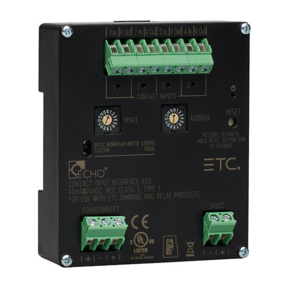
The Echo Contact and Demand Response Interfaces are DIN rail mounted
devices that are available in the following configurations:
Input Interface - accepts four momentary or maintained closures to
•
trigger control actions within an Echo control system.
Demand Response Interface - accepts four maintained closures to
•
trigger demand response within an Echo control system.
Output Interface - provides four normally open or normally closed
•
output relays controlled by actions in the Echo control system.
Contact Input
Custom Configuration
This document guides you through the installation and basic local
configuration settings of the interface devices. Information about custom
configuration options available using EchoAccess are available in the app
integrated help system.
Note:
the unit must be placed in Custom configuration mode. See
Configuration Mode on
Accessory Kits
ETC offers a Low Voltage DIN rail Cover Kit (part number 7186A1218) that
allows installation of the Contact and Demand Response Interfaces to a
10.16 cm (4 in) junction box (provided by others). Contact ETC for ordering
details.
Demand Response
To use the configuration settings applied using EchoAccess,
page 5.
Corpora te He a dqua rte rs Middleton, WI, USA +1 608 831 4116
London, UK +44 (0)20 8896 1000 Holzk irc he n, DE +49 (80 24) 47 00-0
Rome , IT +39 (06) 32 111 683 Hong Kong +852 2799 1220 P a ris, FR +33 1 4243 3535
We b
etcconnect.com
Conta c t
etcconnect.com/contactETC
Product information and specifications subject to change. ETC intends this document
to be provided in its entirety. Trademark and patent
7 1 8 6 M 2 1 4 4 Rev C Released 2020-04
Support
support.etcconnect.com
© 2020 Electronic Theatre Controls, Inc.
Contact Output
Set
info: etcconnect.com/ip
Advertisement
Table of Contents

Related Manuals for ETC Echo Contact Input


Summary of Contents for ETC Echo Contact Input
- Page 1 Accessory Kits ETC offers a Low Voltage DIN rail Cover Kit (part number 7186A1218) that allows installation of the Contact and Demand Response Interfaces to a 10.16 cm (4 in) junction box (provided by others). Contact ETC for ordering details.
-
Page 2: Prepare For Installation
• WEEE marked • RoHS Compliance • For use with ETC Echo Control Systems, powered by an Echo station power supply. Control Requirements EchoConnect Echo interface devices require an ESD ground connection and EchoConnect, which supporting control signal between the device and the connected Echo control system. -
Page 3: Installation
ETC Installation Guide Contact and Demand Response Interfaces Input and Demand Response Interface Wire Terminations The Contact Input and Demand Response Interfaces provide four sets of terminals (“In” and “V out”) for connection to a momentary (Input Interface only) or maintained contact input. Terminals accept 0.2 mm... - Page 4 ETC Installation Guide Contact and Demand Response Interfaces the terminal labeled “+”. Secure the screws firmly onto each wire. Connect EchoConnect Strip 9-10 mm (3/8 in) of insulation from the bare end of the Belden 8471 (or equivalent) wires and the ESD ground wire.
- Page 5 Use EchoAccess to assign a different Preset for the contact. Note: Particularly when considering machine driven applications, ETC recommends a minimum of 500 ms between any input changes to ensure transitions are reliably applied. Demand Response Interface: Activates Demand Response, affecting up four consecutive Echo Spaces, starting with the interface Space rotary switch setting.
- Page 6 ETC Installation Guide Contact and Demand Response Interfaces Note: Functionality varies depending on whether the normally open or normally closed contact terminal is utilized. The default behaviors listed below are assuming a normally open installation. The normally closed contact provides inverted behavior, its status always the opposite of the normally open contact.
- Page 7 ETC Installation Guide Contact and Demand Response Interfaces Set Space and Address / Zone Start Interface devices participate in an Echo control system using the configured Space and Address / Zone which are selectable using the rotary switches on the front of the unit. By default, these switches are set to Space 1, Address / Zone 1.
-
Page 8: Led States
ETC Installation Guide Contact and Demand Response Interfaces Power Up All EchoConnect terminations in the system must be made before applying power to the system and interface. When the interface is powered up, the power LED will indicate in blue.