
Related Manuals for Ingersoll-Rand Q60P3


Summary of Contents for Ingersoll-Rand Q60P3
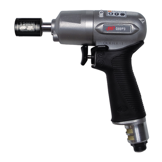
- Page 1 80213671 Edition 2 October 2012 Air Impulse Wrenches Q60P3, Q60PQ1, Q70P3, Q70PQ1, Q80P3, Q80PQ1, Q90P3, Q110P4, Q120P4, and Q140P4 Maintenance Information Save These Instructions...
- Page 2 (70) off the Drive Shaft (51) and remove the Bit Retaining Ball (71). Continue here for Models Q60PQ1, Q70PQ1 and Q80PQ1 Step 1 for Models Q60P3, Q70P3, Q80P3, Q90P3 and Q110P4 Using copper covered vise jaws, carefully grasp the Flats of the Hammer Case (65) with the output end of the Drive Shaft downward.
- Page 3 (74). Lift the Spring Seat, the Spring and the Bit Retaining Sleeve (70) off the Drive Shaft (51) and remove the Bit Retaining Ball (71). - Continue here for Models Q60PQ1, Q70PQ1 and Q80PQ1 - Step 1 for Models Q60P3, Q70P3, Q80P3, Q90P3 and Q110P4 (Dwg. TPD1267) Using copper-covered vise jaws, carefully grasp the Flats of 8.
- Page 4 Reverse Lever Pin (25) out of the Reverse Lever. Separate the Reverse Lever from the Reverse Valve. 8. For Models Q60P3, Q70P3, Q70PQ1, Q80P3, Q80PQ1, and Q90P3, using a punch, tap the Rubber Pad (15) of the Throttle Valve Assembly in order to push the Throttle Bushing Cap (18a) out of the back of the Throttle Bushing.
- Page 5 For Models Q60P3, Q70P3, Q70PQ1, Q80P3, Q80PQ1 and Vane Q90P3, place the Ball (18b) and Spring (17a) in the back of the Cylinder Throttle Valve (14). Place the Rubber Pad (15) on the front of the Throttle Valve. Insert the Throttle Valve Assembly into the back of the Throttle Bushing (11).
- Page 6 20. After installing the Lower Plate Spacer, grasp the shaft of the 7. Compress the Springs with the Blades until both Blades are flush Rotor and rotate it by hand. If the Rotor does not turn easily, with the Drive Shaft. Install the Liner over the assembly, lining up disassemble the motor unit and determine where the assembly is the two Pins (48) with the holes in the Liner Lower Plate.
- Page 7 Y-0181-0990-0003 Q90P3 Pressing Sleeve - Jig C Y-0187-0990-0003 Q110P4 O-Ring Installer - Jig E 45P-E-PSS Q60P3, Q60PQ1, Q70P3, Q70PQ1, Q80P3, Q80PQ1, Q90P3, Q110P4 Spanner - Jig F Y-0189-0990-0006 Q60P3, Q60PQ1, Q70P3, Q70PQ1, Q80P3, Q80PQ1 Spanner - Jig F Y-0188-0990-0006 Q90P3...
- Page 8 © 2012 Ingersoll-Rand, plc...
Need help?
Do you have a question about the Q60P3 and is the answer not in the manual?
Questions and answers