
Subscribe to Our Youtube Channel
Related Manuals for GHM Delta OHM HD2328.0


Summary of Contents for GHM Delta OHM HD2328.0
- Page 1 English Operating manual Thermocouple Thermometer HD2328.0 Companies / Brands of GHM www.deltaohm.com Keep for future reference.
-
Page 2: Table Of Contents
CONTENTS GENERAL CHARACTERISTICS ..........................3 DESCRIPTION OF THE FUNCTIONS ....................... 6 THE PROGRAMMING MENU ..........................9 PROBES AND MEASUREMENTS ........................10 EMPERATURE EASUREMENT ........................... 10 ) ................. 10 ALIBRATION OF THE INSTRUMENT ON LINE WITH THE PROBE – I ): .............. 11 ALIBRATION SEQUENCE NSTRUMENT ON LINE WITH THE PROBE WARNINGS ................................ -
Page 3: General Characteristics
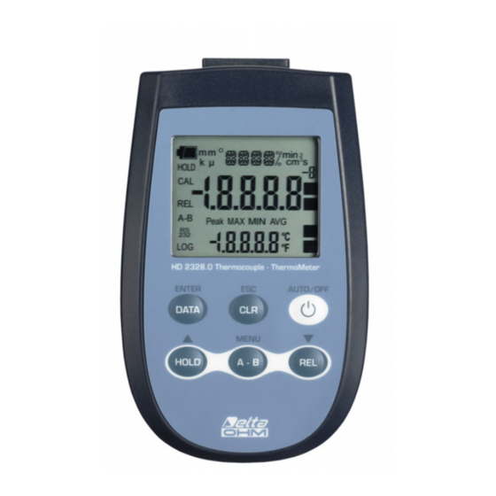
GENERAL CHARACTERISTICS The Thermocouple Thermometer Model HD2328.0 is a portable instrument with two inputs A and B. It measures the temperature of the two input channels, and can calculate the difference between the two channels (A-B). It is fitted with a large LCD display for excellent visualization of the measured data. The Thermometer Model HD2328.0 measures the temperature using immersion, penetration, contact or air probes. - Page 4 Thermocouple Thermometer HD2328.0 - 4 - HD2328 V1.7...
- Page 5 HD2328.0 1. Inputs A and B for two thermocouples, with standard miniature connectors. 2. Battery symbol: displays the battery charge level. 3. Function indicators. 4. Secondary display line. 5. DATA/ENTER key: during normal operation displays the maximum (MAX), the minimum (MIN) and the average (AVG) of current measurements; in the menu, confirms the current selection.
-
Page 6: Description Of The Functions
DESCRIPTION OF THE FUNCTIONS The keyboard of the Thermocouple Thermometer Model HD2328.0 is composed of double-function keys. The function on the key is the "main function", while the one above the key is the "secondary function". When the instrument is in standard measurement mode, the main function is active. In the menu, the secondary function is enabled;... - Page 7 DATA/ENTER key The DATA key is used for the following functions: DATA: during normal measurement, by pressing this key once the maximum • (MAX) value of the measurements captured by the probes connected to the instrument is displayed, updating it with the acquisition of new samples; - by pressing this key again the minimum (MIN) value is displayed;...
- Page 8 A-B/MENU key The A-B key is used for the following functions: A-B: in measurement mode, it displays in the secondary line the difference of the • temperatures measured by the probes connected to the inputs A and B, and indicates "ERR" if one of the probes is in error (not connected, faulty or overrange).
-
Page 9: The Programming Menu
THE PROGRAMMING MENU To access to the programming menu press simultaneously the DATA+(A-B) keys. The items to be set are listed in this order: 1. Selection of the unit of measurement: the "SEL_MEAS_UNIT" message is displayed in the comment line. The main line in the center of the display shows the selected unit of measurement: Celsius (°C) or Fahrenheit (°F) degrees.: use the ... -
Page 10: Probes And Measurements
PROBES AND MEASUREMENTS The instrument works with thermocouple probes of type K, J, T, or E. See chapter ‘The programming menu’ for the selection of the type of probe. The contacts of the thermocouple probe connector are polarized. They must be inserted on the standard miniature socket located on the instrument in the correct direction. -
Page 11: Calibration Sequence - Instrument On Line With The Probe ( S )
The calibration information is saved in the instrument's memory. The same correction is applied to any probe that is subsequently connected to the input: therefore, the "USER calibration" should only be used with the probe used for calibration and not with other probes. -
Page 12: Warnings
WARNINGS 1. Do not expose the probes to gases or liquids that could corrode the material of the probe. Clean the probe carefully after each measurement. 2. Do not bend the probe connectors or force them upward or downward. 3. Comply with the correct polarity of the probes. 4. -
Page 13: Instrument Signals And Faults
INSTRUMENT SIGNALS AND FAULTS The following table lists all error indications and information displayed by the instrument and supplied to the user in different operating situations: Display indications Explanation Correct the first point using the arrows / 1ST_MEAS UP DOWN Correct the second point using the arrows /... -
Page 14: Low Battery Warning And Battery Replacement
LOW BATTERY WARNING AND BATTERY REPLACEMENT The battery symbol on the display constantly shows the battery charge status. To the extent that batteries have discharged, the symbol "empties". When the charge decreases still further it starts blinking. In this case, batteries should be replaced as soon as possible. If you continue to use it, the instrument can no longer ensure correct measurement. -
Page 15: Notes About Working And Operative Safety
NOTES ABOUT WORKING AND OPERATIVE SAFETY Authorized use The technical specifications as given in chapter “TECHNICAL CHARACTERISTICS” must be observed. Only the operation and running of the measuring instrument according to the instructions given in this operating manual is authorized. Any other use is considered unauthorized. -
Page 16: Instrument Technical Characteristics
INSTRUMENT TECHNICAL CHARACTERISTICS Instrument Dimensions (Length x Width x Height) 140 x 88 x 38 mm Weight 160 g (complete with batteries) Material Display 2x4½ digits plus symbols Visible area: 52 x 42 mm Operating conditions Operating temperature -5…+50°C Warehouse temperature -25…+65°C Working relative humidity 0…90% RH without condensation... - Page 17 The tolerance of a type of thermocouple corresponds to the maximum acceptable departure from the e.m.f. of any thermocouple of that type, with reference junction at 0°C. The tolerance is expressed in degrees Celsius, preceded by the sign. The percentage tolerance is given by the ratio between the tolerance expressed in degrees Celsius and the measurement junction temperature, multiplied by one hundred.
-
Page 18: Ordering Codes
ORDERING CODES HD2307.0 The kit is composed of the HD2328.0 with two inputs, 3 1.5V alkaline batteries, operating manual, and case. The probes must be ordered separately. HERMOCOUPLE PROBES The thermocouple probes can be connected to all instruments using the standard miniature connector, which can be obtained from the price list. - Page 20 GHM GROUP – Delta OHM | Delta Ohm S.r.l. a socio unico Via Marconi 5 | 35030 Caselle di Selvazzano | Padova | ITALY Phone +39 049 8977150 | Fax +39 049 635596 www.deltaohm.com | sales@deltaohm.com WARRANTY Delta OHM is required to respond to the "factory warranty" only in those cases provided by Legislative Decree 6 September 2005 - n.
Need help?
Do you have a question about the Delta OHM HD2328.0 and is the answer not in the manual?
Questions and answers