
Related Manuals for Parker Zander AKM 1


Summary of Contents for Parker Zander AKM 1
- Page 1 Oil vapour adsorber AKM 1-8 / 3D ( Generation - 3 ) Operating manual Revision 00—2018 /EN Cod: 398H272179...
-
Page 3: Table Of Contents
EN | User Manual Index Machine passport General information Manufacturer’s details ......................4 Details on the dryer ........................4 About these operating instructions ................... 5 For your own safety General safety notes ......................... 6 Intended use of the adsorber ....................7 Signs and hazard areas on the adsorber ................. - Page 4 EN | User Manual AKM 1-8/D3...
-
Page 5: Machine Passport
EN | User Manual Machine passport Machine passport It is the responsibility of the owner, ◊ to enter for the fi rst time any appliance data not stated above, ◊ to keep these appliance data up to date. The above-stated appliance data provide for a clear identifi cation of the adsorber and its components, and signifi cantly facilitate any service measures. -
Page 6: General Information
General information Manufacturer’s details Name and address Parker Hannifi n Manufacturing S.r.l. Sede Legale: Via Privata Archimede, 1- 2009 Corsico (MI) Italy Sede Operativa: Gas Separation and Filtration Division EMEA - Strada Zona Industriale, 4 35020 S.Angelo di Piove (PD) Italy tel +39 049 971 2111- fax +39 049 9701911 Web-site: www. -
Page 7: About These Operating Instructions
EN | User Manual General information About these operating instructions These operating instructions contain basic information on the safe use of the adsorber. Characters and symbols used Work steps that you have to carry out in the sequence stated are marked by black tri- angles. -
Page 8: For Your Own Safety
EN | User Manual For your own safety For your own safety The adsorber has been built in accordance with the state of the art and the recognized technical safety regulations. Nevertheless, there is a risk of personal injury and damage to property when the adsorber is used, if ◊... -
Page 9: Intended Use Of The Adsorber
EN | User Manual For your own safety Disassembly and disposal ◊ Dispose all parts of the adsorber, the purifying agents and all other operating materials in an environmentally safe way and in accordance with all current statutory regulations. Intended use of the adsorber The adsorber is exclusively intended for purifying compressed air. -
Page 10: Signs And Hazard Areas On The Adsorber
EN | User Manual For your own safety Signs and hazard areas on the adsorber Signs and labels Type plate of downstream fi lter Type plate of adsorber Front view Please note these signs on the adsorber. Keep them complete and always legible AKM 1-8/D3... - Page 11 EN | User Manual For your own safety Hazard areas on the adsorber Hazard caused by overpressure Risk of damage to eyes Front wiew Symbol Hazard area Warning against overpressure The entire adsorber is under pressure. Before commencing any work, the plant must be depressurised.
-
Page 12: Transportation, Installation And Storage
EN | User Manual Transportation, installation and storage Transportation, installation and storage Danger due to incorrect transportation! The adsorber must be transported by authorized and qualifi ed specialist personnel only. During transportation all applicable national regulations for ac- cident prevention must be complied with. Otherwise there is a risk of personal injury. -
Page 13: Transporting And Installing The Adsorber
EN | User Manual Transportation, installation and storage Transporting and installing the adsorber Requirements for the installation site The conditions at the installation site have a large infl uence on the functional capacity of the adsorber and the service life of the purifying agent. In order to ensure a mode of operation, which is as continuous as possible, and low maintenance, the installation site must meet the following requirements: ◊... - Page 14 EN | User Manual Transportation, installation and storage Secure the cardboard box or pallet on the lifting or forklift truck against sliding move- ments. Transport the adsorber to its installation site. Remove the packaging of the adsorber. Adsorber on transportation pallet AKM 1-4: Adsorber in a cardboard box Note the weight of the Adsorber!
-
Page 15: Storing The Adsorber
EN | User Manual Transportation, installation and storage Storing the adsorber If the adsorber is to be stored for an extended period of time, the storage location must meet the following conditions: ◊ The adsorber must not be stored in the open air. ◊... -
Page 16: Technical Product Description
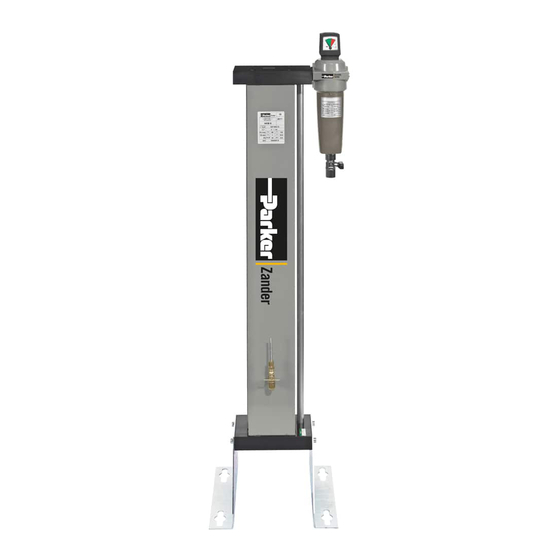
EN | User Manual Technical product description Technical product description Summary drawing Front view Top plate Compressed air outlet Compressed air inlet Downstream fi lter Oil indicator Single chamber hollow section vessel Base plate Function description The pre-dried compressed air is fed into the adsorber, where oil vapour and other contami- nants are removed from the compressed air, which is then made available for industrial use. -
Page 17: Installation
EN | User Manual Installation Installation Only authorized and qualifi ed specialist personnel may carry out work on pipes. As soon as the adsorber has been set up at its installation location, you can install the com- pressed air infeed and outlet lines. Preconditions for installation For a correct installation the following preconditions must be met on the part of the owner. -
Page 18: Connect Piping
EN | User Manual Installation Connect piping In order to ensure that the adsorber operates optimally, the adsorber must be assembled into the compressed air system free of all stresses. Ensure before connection that all infeed and outfeed compressed air lines and valves are clean and undamaged. -
Page 19: Start-Up
EN | User Manual Start-up Start-up Hazard due to a sudden release of pressure! Never remove any parts of the adsorber, or manipulate the same in any way, for as long as the plant is still pressurised! A sudden escape of pressure may cause serious injuries. -
Page 20: Overview Of Operating And Control Elements
EN | User Manual Start-up Overview of operating and control elements Oil indicator The adsorber is equipped with an oil indicator. The indicator allows for periodic measuring of the residual oil concentration in the purifi ed compressed air. The residual oil content should only be measured at set intervals, and the needle valve (1) at the indicator should be closed during normal operation. - Page 21 EN | User Manual Start-up Slowly open the compressed air inlet valve, installed by the owner, upstream of the adsor- ber. Open compressed air outlet line Slowly open compressed air outlet valve! Avoid sudden pressure build-up in any circumstance! If pressure builds up too fast, this may cause damage to the adsorber.
-
Page 22: Monitoring Adsorber Operation
EN | User Manual Monitoring adsorber operation Monitoring adsorber operation ◊ Only operate the adsorber within the permissible limits (see type plate). By operating the adsorber in conditions that go beyond the defi ned values, the ad- sorber is subjected to loads for which it has not been designed. This may cause functional defects. -
Page 23: Shutdown And Restart Adsorber
EN | User Manual Shutdown and restart adsorber Shutdown and restart adsorber In the following cases, the adsorber must be fully shut down and depressurised: ◊ In the event of an emergency or malfunction ◊ For maintenance work ◊ For dismantling Risk of injury from escaping compressed air! Never remove any parts of the adsorber, or manipulate the same in any way, as long as the unit is pressurised! Suddenly escaping compressed air might cause... -
Page 24: Restart
EN | User Manual Shutdown and restart adsorber Restart Commission adsorber as described on page 18 . After the purifying agent has been replaced The newly fi lled purifying agent contains minute dust particles that can block the downstream fi lter (option) or other components. We therefore recommend to complete the following steps before you restart the adsorber, in order to protect your equipment: Open relief valve (installed by the owner) downstream of the adsorber, or Remove the housing base and the fi lter element from the downstream fi lter. -
Page 25: Maintenance And Repair Of The Adsorber
EN | User Manual Maintenance and repair of the adsorber Maintenance and repair of the adsorber In order to allow maintenance work on the adsorber to be carried out effi ciently and without danger for maintenance personnel, you should comply with the following instructions. Notes on maintenance Warning! Maintenance tasks may be carried out only by authorized and qualifi... -
Page 26: Regular Maintenance Intervals
EN | User Manual Maintenance and repair of the adsorber Regular maintenance intervals Note: If a chamber has been depressurised and the pressure remains above 0 bar, the chamber is pressurised by what is known as ram pressure. This might be due ◊... -
Page 27: Daily Maintenance Tasks
EN | User Manual Maintenance and repair of the adsorber Daily maintenance tasks Carry out visual and function check on the complete adsorber Check adsorber for external damage or unusual noise generation. Duly eliminate any defects found. Clean adsorber Remove any loose dust by means of a dry cloth, and, if required, also by means of a moist and well wrung cloth. - Page 28 EN | User Manual Maintenance and repair of the adsorber Measuring procedure Prepare measuring log and hold it ready. Check union nut holding the indicator tube and retighten, if necessary. At the indicator tube, mark the highest segment with a colour change, using a suitable pen.
- Page 29 EN | User Manual Maintenance and repair of the adsorber Note: The evaluation is based on a pressure-reduced partial fl ow that is fed into the indicator tube at a pressure of 7 bar operating pressure. For adsorbers with an operating pressure of less than 7 bar, please refer to the respective table in the appendix (for 4, 5 or 6 bar operating pressure).
- Page 30 EN | User Manual Maintenance and repair of the adsorber Replacing indictor tube Risk of damage to eyes! If not properly secured, the indicator tube might be propelled out of its holder! When the needle valve is opened, the indicator tube is secured by a union nut.
-
Page 31: Maintenance Work To Be Completed Every 12 Months
EN | User Manual Maintenance and repair of the adsorber Maintenance work to be completed every 12 months Replace perforated plate and purifying agent To complete the following maintenance tasks, you must dismantle the plates and the vessels. We therefore recommend that you carry out these tasks together. The active surface of the purifying agent can be reduced by oil residue and other contami- nants. - Page 32 EN | User Manual Maintenance and repair of the adsorber Caution! The spent purifying agent might be contaminated with hazardous substances. Dispose of it in an environmentally safe manner, taking into account possible contamination. The waste code number of the purifying agent can be obtained from the manufacturer.
-
Page 33: Identify And Eliminate Faults
EN | User Manual Identify and eliminate faults Identify and eliminate faults Summary of faults Faults on the adsorber become noticeable e.g. due to unusual noises and ram pressures. The following table shows who is allowed to remedy a fault: the owner’s specialist personnel or the manufacturer’s service engineer. -
Page 34: Annex With Technical Documentation
EN | User Manual Annex with technical documentation Annex with technical documentation This annex comprises the following information and technical documentation: ◊ Technical data ◊ Replacement and wear parts list ◊ Technical documents of the oil indicator ◊ Flow diagram ◊... -
Page 35: Technical Data
EN | User Manual Annex with technical documentation Technical data Operating Range Site Selection frost-free indoor installation in a non-hazardous environment Ambient temperature 1,5 to 50 °C (34,7 to 122 °F) Compressed air inlet temperature 25 to 50 °C (68 to 122 °F) Max. -
Page 36: Replacement And Wear Part List
EN | User Manual Annex with technical documentation Replacement and wear part list Note: When exchange or replacement parts are ordered, always state the dryer type and the build no. of the Adsorber. These data are found on the type plate. Service-kits Order ID For model... - Page 37 EN | User Manual Annex with technical documentation Evaluation tables for determination of the residual oil content At 4 bar operating pressure Duration Number of fi rst-ever coloured scale units 1.00 1.95 2.90 3.85 4.90 5.95 6.75 7.50 0.90 1.75 2.55 3.40 4.35...
- Page 38 EN | User Manual Annex with technical documentation At 5 bar operating pressure Duration Number of fi rst-ever coloured scale units 0.80 1.55 2.35 3.15 3.90 4.80 5.55 6.25 0.72 1.40 2.10 2.75 3.50 4.25 4.90 5.60 0.62 1.25 1.85 2.50 3.15 3.75...
- Page 39 EN | User Manual Annex with technical documentation At 6 bar operating pressure Duration Number of fi rst-ever coloured scale units 0.65 1.30 1.95 2.60 3.25 3.85 4.75 5.40 0.62 1.20 1.70 2.20 2.80 3.55 4.10 4.75 0.52 1.05 1.55 2.10 2.60 3.25...
- Page 40 EN | User Manual Annex with technical documentation Flow diagram Item Designation Item Designation Seal Oil indicator Perforated Plate Optional devices: Top Plate Upstream fi lter Base plate Downstream fi lter AKM 1-8/D3...
-
Page 41: Installation On Fl Oor
EN | User Manual Annex with technical documentation Installation on fl oor Installation on fl oor BSP-P/ Dimensions [mm] Weight [kg] Type AKM 1 1/4" AKM 2 1/4" AKM 3 1/4" 10,0 AKM 4 1/4" 1075 1051 12,0 AKM 6 1/2"... - Page 42 EN | User Manual AKM 1-8/D3...
- Page 44 A division of Parker Hannifin Corporation Parker Hannifin Manufacturing S.r.l. Sede Legale: Via Privata Archimede, 1- 2009 Corsico (MI) Italy Sede Operativa: Gas Separation and Filtration Division EMEA - Strada Zona Industriale, 4 35020 S.Angelo di Piove (PD) Italy tel +39 049 971 2111- fax +39 049 9701911 Web-site: www.
Need help?
Do you have a question about the Zander AKM 1 and is the answer not in the manual?
Questions and answers