Table of Contents
Advertisement
Quick Links
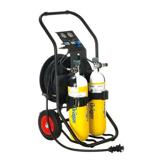
Dräger PAS AirPack 1 Trolley Module
Airline Compressed Breathing Air Supply System
Approvals
The Dräger PAS AirPack 1 Trolley Module conforms to the requirements of EN139 and meets the
requirements of EC Council Directive PPE (89/686/EEC) and PED (97/23/EC).
PPE – EC Type examiner; SGS United Kingdom Limited, Unit 202b, Worle Parkway, Weston-super-
Mare, BS22 0WA, UK. Notified Body No. 0120. CE Mark approved and issued with EC Type Examination
Certificate.
PED – EC Type examiner; Lloyds Register, Hiramford, Middlemarch, Office Village, Siskin Drive, Coventry,
CV3 4FJ, England. Notified Body No. 0038. The equipment is manufactured in accordance with the
requirements of Conformity Assessment Trolley Modules B + D of the Pressure Equipment Regulations.
A copy of the Declaration of Conformity is available from Dräger on request.
For Your Safety
The Dräger PAS AirPack 1 Trolley Module incorporates a high performance pressure reducer. The reducer
is factory set and must not be tampered with, or removed from the manifold, as this invalidates the
conditions of the Dräger warranty. Correct operational condition is valid only if Dräger service and re-
seals the pressure reducer.
u Use of this equipment requires wearer training and observance of these Instructions for Use and the
Instructions for Use supplied with the selected associated breathing equipment.
u Use the equipment for the purpose specified in this instruction, or as confirmed in writing by Dräger.
u Use and maintenance of this equipment requires knowledge and compliance with National Regulations,
Laws and Standards governing the use of respiratory equipment in the country of use.
u Only trained competent personnel should inspect and service the equipment at regular intervals and
a record kept of such inspections and service.
u Only trained and competent personnel should carry out the charging of the compressed air cylinders.
u Dräger recommends that a Service Contract be obtained from your Dräger Branch or Agent.
u Contact Dräger for details of Service Contracts and Service Training Courses.
u Use only original Dräger Spare Parts for service and maintenance.
u Use only original Dräger Test Equipment for service and maintenance.
u Notify Dräger if there is a component fault or failure.
Liability Statement
Terms and Conditions of warranty for the Dräger PAS AirPack 1 Trolley Module can be obtained from Dräger
on request. Responsibility for reliable function of the equipment transfers to the owner or operator when
serviced or repaired by untrained personnel, (not employed or authorised by Dräger), or when used in a manner
not conforming to its intended use.
Description and Intended Use
Main Airline Pressures and Flow
The Dräger PAS AirPack 1 Trolley Module is a
Safety Note: In order for the Trolley Module to
compact mobile two-wheel trolley unit with
function efficiently, it is the responsibility of
flexible rubber airline hose and hose winding drum,
the user to ensure that the following air
plus storage capacity for two valved high-pressure
pressure and flows are available from the
cylinder assemblies. The module provides a low-
factory mains airline air source. Air quality
pressure independent breathing air supply to the
for compressed air breathing systems must
wearer of approved Dräger breathing apparatus
conform to the requirements of EN12021.
fitted with airline manifold connections.
The selected LP independent air supply must meet
The equipment is compatible with a range of
the following parameters.
associated breathing apparatus and
accessories and must be used only with air that
u One User – 7bar to 10bar - airflow rate of at
complies with the air quality requirements of
least 550 Litres/minute.
respirable breathable air at the pressure and
u Two Users – 7bar to 10bar - airflow rate of
quantities (volumes) required. When the airline
at least 550 Litres/minute.
fitting of the breathing apparatus is connected
to the module, the approved configuration
LP Leak Test - Indicated pressure should not
provides the wearer with respiratory protection
decrease more than 1bar in one minute.
when working in a contaminated or oxygen
deficient gaseous atmosphere.
Preparation for Use
The manifold assembly of the module allows for
Only trained and competent personnel must
the repeated removal and fitting of cylinders,
perform the following checks and preparation
transferring of air supply from one cylinder to
procedures before release of the equipment for
another. This feature provides a means of
operational use to a 'Controller' and potential
providing an uninterrupted air supply to the
breathing apparatus 'Wearer'.
wearer.
Visual Inspection
Automatic activation of a preset mechanical high
pressure whistle warning unit (HPWWU) alerts
Check the cleanliness and integrity of,
the Controller of low cylinder pressure. Activation
u Trolley frame and wheels.
of a low pressure whistle warning unit (LPWWU)
u Cylinder support straps (2).
alerts the Controller of a drop in pressure of the
u Winding Drum and low pressure hose.
low-pressure air supply.
u Pneumatics, Gauges, WWU’s, Quick Release
Coupling(s) (QRC) etc.
If required, the cylinders may be bypassed by
u HP hoses and cylinder connector handwheel
connecting the inlet coupling of the trolley
assemblies (2).
module to an independent low-pressure air
supply, e.g. from a works airline or LP
Fitting the Cylinders
compressor (refer to Main Airline Pressures and
u Place the AirPack 1 Trolley Module in the upright
Flow and Air Quality requirement . A drop in
position as shown in Fig. 1.
low air supply pressure is highlighted to the
u Check that the valve outlet port of each fully
Controller by the activation of an audible low
charged valved cylinder is clean and
pressure whistle warning unit (LPWWU).
undamaged. Place each cylinder through the
loop of each of the cylinder straps locating the
The possible available extended working duration,
rounded end of the cylinders into the cylinder
depends on the configuration selected (attached to
cradle supports at the base of the trolley frame.
works airline or LP compressor - with filter unit to
u Check that both connector handwheels are not
maintain air quality), the capacity (volume) of
damaged and that the connector O rings are
cylinder(s) selected, the number of fully charged
in position and not damaged.
cylinders available and the breathing rate of the
u Rotate the cylinders to align the outlet port of
wearer(s).
each valve with the associated connector
handwheel assembly. Ensure a smooth curve
Important Note: No more than two users of
of the high-pressure hose. Screw each
approved airline breathing equipment
handwheel into the appropriate cylinder valve
should be connected to the AirPack 1
– hand tight.
Trolley Module at any time, and in any
u Take up slack of each of the cylinder support
configuration. Refer to the Equipment
straps then activate the Camlock mechanism
Configuration details chart.
by pulling the free end of the support strap
around the cylinder - securing each cylinder
Details of equipment variants, associated
to the frame. Fig. 1.
breathing equipment and accessories are
available from Dräger on request.
Leak Test and Test of WWU’s
Technical Data
u 'Close' both the high-pressure (HP) bleed
High Pressure Connections
valves (6) of the cylinder connector
Standard G5/8 as per EN 144-2.
handwheel assemblies - handtight.
200bar or 300bar.
u 'Open' slowly, but fully, ONE of the cylinder
valves to pressurise the system. Check the
Other high-pressure (HP) connections are
indicated pressure readings on the HP gauge
available to National Standards.
(2) and the LP gauge (3).
High Pressure - Indicated pressure should be
Operating Pressure
at least 80% of maximum working pressure
Low Pressure - 8bar Nominal. (6bar to 10bar)
indicated on the selected cylinders.
Low Pressure - Indicated pressure should be
Whistle Warning Units (WWU)
between 6bar to 10bar.
HPWWU - Preset between 60bar to 50bar
u 'Open' the HP bleed valve (6) of the connector
LPWWU - Preset between 3bar to 5bar
handwheel assembly of the opposite cylinder
(i.e. the ‘Closed’ valve) – there should be no
Compressed Air Cylinders
audible leak. If satisfactory 'Close' the HP
Contact Dräger for details of approved valved
bleed valve.
compressed air cylinder assemblies available for
u 'Close' the cylinder valve.
use with this equipment.
seconds to allow the system to stabilise then
check the pressure reading on the HP gauge
Important Note: Only matched pairs of cylinders
(2) and the LP gauge (3).
should be fitted to the Dräger AirPack 1 Trolley
Module, e.g. 2 x 9 litres 200bar. Do Not mix
HP Leak Test - Indicated pressure should not
200bar and 300bar cylinders.
decrease more than 20bar in one minute.
u Following satisfactory leak test, check the
activation of the HPWWU (1) and the LPWWU
(4) as follows:
Slowly vent pressure from the HP side of the
system by gripping and carefully pulling the
handle of the relief valve (7). As the pressure
decreases observe the HP gauge (2) .
HPWWU - the whistle should begin to sound
between 60bar to 50bar. As soon as the whistle
sounds, release grip on the handle of the relief
valve (7) and allow the whistle to vent. When
the HPWWU stops sounding proceed
immediately to test the LPWWU.
u Following satisfactory HPWWU test, check the
activation of the LPWWU as follows:
Again grip and carefully pull the handle of the
relief valve (7). As the pressure decreases
observe the LP gauge (3) .
LPWWU - the whistle should begin to sound
between 5bar to 3bar.
u Check the HP bleed valves (6) at each cylinder
valve are 'Closed' then slowly, but fully, 'Open'
the second cylinder valve to pressurise the
system. Check the indicated pressure readings
on the HP gauge (2) and the LP gauge (3).
High Pressure - Indicated pressure should be
at least 80% of maximum working pressure
indicated on the selected cylinders.
Low Pressure - Indicated pressure should be
between 6bar to 10bar.
u Open the high-pressure bleed valve (6) of the
connector handwheel assembly of the opposite
(first) cylinder (i.e. the ‘closed valve.) – there
should be no audible leak. If satisfactory 'Close'
the bleed valve.
u 'Close' the cylinder valve and then check the
pressure reading on the HP gauge (2).
High Pressure Leak Test - Indicated pressure
should not decrease more than 20bar in one
minute.
u Following satisfactory completed tests, grip and
pull the handle of the relief valve (7) to vent
pressure from system.
u Having ‘passed’ the tests, the equipment is now
available for use.
Pre-Use Procedures
Caution: Before connecting the selected airline
breathing equipment to the tested and released
Dräger
PAS AirPack 1
Trolley Module, ‘check’
that the breathing equipment has been tested
by a trained and competent person before
being released for use. When in use the
AirPack 1
Trolley Module must be positioned
in a safe and uncontaminated area. Dräger
recommend that a ‘Controller’ must be present
at all times to monitor and maintain the air
supply to the wearer of the selected breathing
equipment. Time required for the wearer of
the airline breathing equipment to safely
evacuate from the hazardous area to a safe area
must be within the air capacity of the remaining
cylinder(s) of the
PAS AirPack 1
Trolley Module.
Dräger recommend that the user(s) of this final
configuration operate and maintain a ‘Permit
for Use’ procedure and also have an
established company evacuation procedure(s).
The Dräger PAS AirPack 1 Trolley Module may be
used either as a self-contained unit, i.e. using the
attached compressed air cylinders, or by connecting
the module to an independent low-pressure air supply,
e.g. from a works airline or LP compressor the
cylinders can be bypassed.
Self-contained Unit
The Controller
u With the trolley module suitably positioned in a
safe and uncontaminated area, pull and unwind
Wait for 10 to 15
a required length of hose from the winding drum.
Attach any required accessories, e.g. extension
hoses, 'Y' pieces, etc.
u Check that both HP bleed valves (6) at each of
the connector handwheel assemblies are
'Closed' (clockwise).
Instructions for Use
u Continue to breathe normally and as instructed
by the controller proceed to the working area
1
2
3
4
taking care to support and route the airline hose
as necessary.
In Use - When used as a Self-
contained Unit
The Controller
u Regularly take a HP gauge reading. At between
60bar to 50bar the HPWWU unit sounds
indicating that the cylinder in use is almost
empty. To therefore maintain the air supply to
the wearer of the breathing equipment
immediately proceed as follows:
1. Slowly, but fully, 'Open' the valve of the
second fully charged cylinder. The HP gauge
5
6
7
8
(3) will indicate an increase in system pressure.
The wearer is now connected to the fully
charged cylinder.
2. 'Close' the valve of the empty cylinder then
'Open' the bleed valve (6) of the associated
valve to vent the remaining pressure from the
HP supply hose.
3. Unscrew the connector handwheel from the
valve of the depleted cylinder. Release the
Camlock mechanism of the cylinder support
strap and remove the cylinder.
4. Select an available replacement fully charged
cylinder and assemble to the trolley. See -
Preparation for Use – Fitting Cylinders.
1
5. 'Close' the bleed valve (6) of the connector
handwheel assembly of the replacement
1642
cylinder.
Note: To maintain a supply of respirable breathing
When used as Self-contained Unit
air to the wearer of the breathing equipment, this
u 'Open' slowly, but fully, ONE of the cylinder
procedure can be repeated with further available
valves to pressurise the system. Check the
replacement fully charged cylinders.
indicated pressure readings on the HP gauge
(2) and the LP gauge (3).
Safety Warning: Should the LPWWU of the PAS
AirPack 1 Trolley Module sound, then the
High Pressure - Indicated pressure should be
controller must immediately implement the
at least 80% of maximum working pressure
agreed and established company evacuation
indicated on the selected cylinders.
procedure(s).
Low Pressure - Indicated pressure should be
between 6bar to 10bar.
The Wearer – Self Contained Operation
u Breathe normally.
When used from a works airline or
u When the task is completed, or when advised
LP compressor
by the ‘Controller’, proceed to the safe area
(Controller) by the safest route.
Safety Note: Refer to Airline Pressure and
Flow. Air quality must conform to the
Important Note: - Refer to the evacuation
requirements of EN12021. If required use the
procedures as defined in the Instructions for
Dräger Filter Unit.
Use for the selected breathing equipment.
u Connect an approved extension hose from the
In Use - When used from a
selected LP independent air supply to the male
connector (5) of the trolley manifold. 'Open'
Works Airline or LP Compressor
the valve of the independent air supply to
pressurise the system. Check indicated
Safety Note: Refer to Airline Pressure and Flow.
pressure reading on the LP gauge (3).
Air quality must conform to the requirements
of EN12021. If required use the Dräger Filter
Low Pressure - Indicated pressure should be
between 6bar to 10bar.
Unit.
The Controller
The Controller
u Take regular LP gauge (3) reading. The indicated
Important Note: Should the 'Controller' be
pressure should be between 6bar to 10bar.
required to wear respiratory protection
equipment then all the following 'Wearer'
Safety Warning: Should the LPWWU sound,
instructions should be observed. Connect the
indicating a reduction in pressure from the
male coupling of the selected breathing
Works Airline or LP Compressor, the ‘Controller’
equipment to the female QRC (8) of the pressure
must immediately fully 'Open' ONE of the
manifold. This will reduce the duration available
cylinder valves of the
from the selected system. It must be observed
Module to pressurise the system. The extension
however that no more than two users of
hose from the selected LP independent air
approved airline breathing equipment should
supply to the male connector (5) should be
be connected to the PAS AirPack 1 Trolley
disconnected.
Module at any time, and in any configuration.
u Continue to follow the instructions outlined in
The Wearer
the section – i.e. In Use- When used as Self-
u Refer to the Instruction for Use for the selected
contained Unit.
breathing equipment, put on the equipment and
prepare the equipment for attachment and use
The Wearer - Works Airline etc.
with the PAS AirPack 1 Trolley Module.
u Breathe normally.
u Connect the male coupling of the breathing
u When the task is completed, or when advised
equipment to the female QRC of the supply
by the ‘Controller’, proceed to the safe area
hose from the trolley module, i.e. the winding
(Controller) by the safest route.
drum.
Important Note: - If necessary refer to the
Safety Warning: Facial hair, beard stubble,
evacuation procedures as defined in the
side-whiskers, and the wearing of spectacles
Instructions for Use for the selected breathing
will adversely affect and interfere with
equipment.
facepiece seal. Correct fit of facepiece only
ensured if facepiece seal makes close contact
After Use
with skin.
The Wearer
u Put on the facepiece as defined in the Instruction
for Use for the selected breathing equipment,
u Refer to the After Use instructions in the
breathe normally and perform Function Check.
appropriate Instruction for Use for the selected
breathing equipment. Remove the equipment
Function Check
and detach the male coupling of the breathing
equipment from the female QRC of the supply
The Controller
hose of the carrying frame module.
u 'Close' the cylinder valve or the valve of the
Safety Warning: Do Not attempt to remove the
associated air supply.
breathing equipment until in safe area, clear of
the hazard.
The Wearer
u Breathe normally to vent air from the system.
The Controller
During venting the whistle(s) will alarm at the
u Following the removal of the breathing
preset pressure. When fully vented, hold
equipment by the wearer either:
breath. The facepiece should hold onto the face
1.
disconnect the extension hose from the
indicating a positive seal.
selected LP independent air supply from the
u Immediately indicate to the ‘Controller’ of a
male connector (5).
positive face seal and request to immediately
or
‘Open’ the valve of the associated air supply.
2. 'Close' the relevant cylinder valve of the
trolley module.
The Controller
u Grip and pull the handle of the relief valve (7) to
u When ‘Wearer’ indicates to the ‘Controller’ of a
vent pressure completely from system. 'Open'
positive face seal – the ‘Controller’ should
the (HP) bleed valves (6) of the cylinder
immediately ‘Open’ the associated valve to
connector handwheel assemblies
pressurise the system.
u Carefully and neatly rewind the airline hose
to the winding drum. Dräger recommend that
any dirt or contaminants on the hose should
The Wearer – In Use
be removed as it is being rewound onto the
u Inhale and hold breath. The unit must balance,
winding drum.
i.e. no audible leak. Continue to breathe normally.
Expired air should flow easily out of the exhalation
Routine Maintenance
valve of the facepiece. Press the centre of the
rubber cover of the LDV to check for
To be performed after use of the equipment.
supplementary supply airflow then release.
See also Maintenance and Test Intervals Chart.
Refer to the Instructions for Use supplied with the
selected breathing equipment, facepiece, lung
demand valve etc.
Visual Inspection
Check the cleanliness and integrity of,
u Trolley frame and wheels.
u Cylinder support straps (2).
u Winding Drum and LP hose.
u Pneumatics, Gauges, WWU’s, Quick Release
Coupling(s) (QCR) etc.
u HP hoses and cylinder connector handwheel
assemblies (2).
u Associated extension hoses.
Cleaning, Disinfecting, Drying
Dräger recommend that contaminated and dirty
components or assemblies, hoses etc. are
carefully cleaned and disinfected then thoroughly
dried after use, or as considered necessary by the
user.
To ensure correct operational condition of the
equipment use the cleaning and disinfecting
solutions recommended by Dräger. The use of
any other product will invalidate the Dräger
warranty and guarantee.
Safety Note: Refer to manufacturers’ usage
instructions when using cleaning and
disinfecting agents. It is important that
attention be paid to concentration and reaction
times. Do Not use organic solvents, such as
Acetone,
Alcohol,
White
Trichloroethylene or similar.
Dräger recommends the following:
1. Cleaning
u Dräger Safety Wash.
u Sekusept
Do Not exceed a temperature of 30 degrees
Celsius.
Note: Before disinfecting, rinse off cleaning
solution in clean water.
2. Disinfecting
u Incidur
Do Not exceed a temperature of 30 degrees
Celsius.
Note: Before drying, rinse off disinfecting solution
in clean water.
u Dräger Wipex Cloths.
Details of cleaning and disinfecting agents are
available from Dräger on request.
3. Rinsing and Drying
Remove cleaning and disinfecting solutions by
rinsing in clean water, followed by drying.
Do Not exceed a temperature of 60 degrees
Celsius when drying components.
Charging Cylinders
Refer to 'For Your Safety'
Safety Warning: Air quality for compressed air
breathing systems must conform to the
requirements of EN12021.
Only charge compressed air cylinders which:
PAS AirPack 1
Trolley
u Conform to National Standards.
u Feature the original manufacturers test date
and test mark.
u Have not exceeded the test date indicated
on the cylinder by the last testing station.
u Do Not used damaged cylinders.
Recharge to the rated pressure indicated on the
label or stamped on the neck or shoulder of
cylinder. Dräger recommend a charge rate of
27bar/minute. Rapid charging will induce an
increase in temperature resulting in an incomplete
charge - check pressure at ambient and if required
‘Top Up’ charge.
To prevent overcharging of the selected cylinder
Dräger recommend that a pressure-limiting device
is fitted to the charging compressor.
Storage - Ready for Use
u Store the Trolley Module in an upright position
as shown in Fig. 1. A protective dust cover is
available. Contact Dräger for details.
u Store the equipment ‘Ready for Use’ in a cool
dry environment, free from dust and dirt.
Protect rubber parts - Do Not expose to direct
sunlight.
3352691 : 'D' Edition : October 2003 : Subject to Modification
Spirit,
Advertisement
Table of Contents

Subscribe to Our Youtube Channel
Related Manuals for Dräger PAS AirPack 1


Summary of Contents for Dräger PAS AirPack 1
- Page 1 Trichloroethylene or similar. Terms and Conditions of warranty for the Dräger PAS AirPack 1 Trolley Module can be obtained from Dräger on request. Responsibility for reliable function of the equipment transfers to the owner or operator when Note: To maintain a supply of respirable breathing When used as Self-contained Unit Dräger recommends the following:...
- Page 2 Dräger PAS AirPack 1 Trolley Module Instructions for Use Airline Compressed Breathing Air Supply System Fault, Cause, Remedy Maintenance and Test Intervals Dräger recommend that regular Inspection, Testing and Servicing of equipment be carried out in accordance with this table. Record all data in the log book Refer to any associated Instructions for Use supplied with this product, e.g.
Need help?
Do you have a question about the PAS AirPack 1 and is the answer not in the manual?
Questions and answers