Table of Contents
Advertisement
Policy | Procedure
Respiratory protective equipment - breathing apparatus -
Dräger PSS 7000 - technical information
New policy number:
Old instruction number: TEC:B010:b1
Issue date:
Reviewed as current:
Owner:
Responsible work team: RPE and Hazmat PPE
Contents
1
Introduction .................................................................................................................. 3
2
Component parts ........................................................................................................... 6
3
Backplate assembly ........................................................................................................ 9
4
Harness and cylinder strap assembly ................................................................................ 10
5
Telemetry module ........................................................................................................ 11
6
Charging BA set from appliance ...................................................................................... 11
7
FPS 7000 dual purpose face mask ................................................................................... 13
8
Lung demand valve (LDV) ............................................................................................. 15
9
Pneumatic system ........................................................................................................ 16
10
Second person connection............................................................................................. 17
11
Bodyguard 7000 electronic monitoring unit (EMU) ............................................................. 19
12
Bodyguard in use functions ............................................................................................ 20
13
Bodyguard electronic monitoring unit self-check ................................................................ 22
14
SDBA cylinder ............................................................................................................. 23
15
SDBA set - lifting and carrying instructions ....................................................................... 32
16
EDBA cylinder ............................................................................................................. 32
17
EDBA set - lifting and carrying instructions ....................................................................... 36
Review date: 29 January 2023
476
476
17 November 2006
29 January 2020
Assistant Commissioner, Operational Policy
Issue date: 17 November 2006
Last amended date: 5 May 2020
1 of 80
Advertisement
Table of Contents

Related Manuals for Dräger LFB PSS 7000


Summary of Contents for Dräger LFB PSS 7000
-
Page 1: Table Of Contents
Policy | Procedure Respiratory protective equipment – breathing apparatus – Dräger PSS 7000 – technical information New policy number: Old instruction number: TEC:B010:b1 Issue date: 17 November 2006 Reviewed as current: 29 January 2020 Owner: Assistant Commissioner, Operational Policy Responsible work team: RPE and Hazmat PPE Contents Introduction ........................ - Page 2 Receipt test and monthly 28 day test ................37 PSS 7000 ’A’ test ......................38 PSS 7000 ‘B’ test ......................44 Equipment allocation ....................53 Defective equipment ....................54 RPE maintenance rooms ....................56 Technical data ......................57 Glossary RPE generic ......................60 Appendix 1 –...
-
Page 3: Introduction
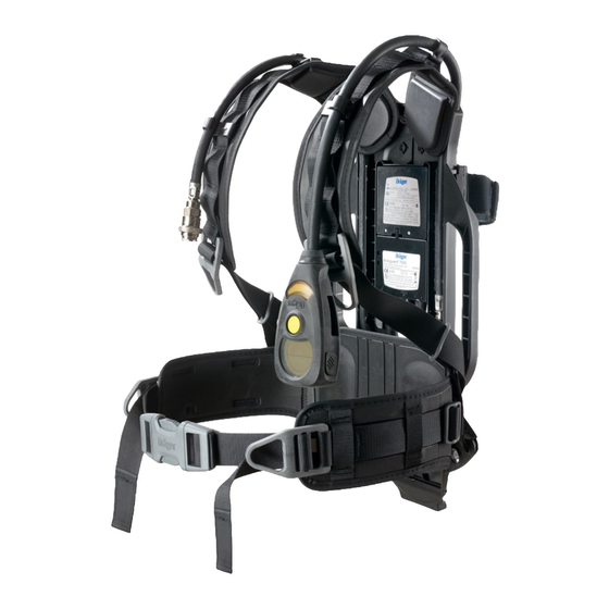
Introduction This policy provides technical information for the Dräger PSS 7000 breathing apparatus (BA) set. Information on breathing apparatus procedures is contained in Policy number 466 – Respiratory protective equipment - breathing apparatus – operational procedures. The PSS 7000 standard duration breathing apparatus (SDBA) set will give a working duration of 31 minutes when applying a consumption rate of 50 litres per minute (LPM). - Page 4 PSS 7000 SDBA set overview FPS 7000 dual purpose face mask Padded shoulder harness Inner mask Lung demand valve, first breath button and additional flow button In-line connection QRC Second person connection QRC Waist belt Bodyguard 7000 user interface unit (display), DSU button and low pressure warning device LFB image id 1136791...
- Page 5 PSS 7000 EDBA set overview FPS 7000 dual purpose face mask Inner mask Padded shoulder harness Lung demand valve, first breath button and additional flow button In-line connection QRC Second person connection QRC Waist belt Bodyguard 7000 user interface unit (display), DSU button and low pressure warning device LFB image id 1136771...
-
Page 6: Component Parts
Component parts The PSS 7000 – component parts (a) Front view SDBA Bodyguard 7000 user interface unit (display). SDBA entry control tally (yellow). Second person connection QRC. Second person hose retaining clip. Cylinder retaining strap and securing mechanism. In-line connection QRC. FPS 7000 dual purpose face mask. - Page 7 (b) Rear view (face mask removed for clarity) 17. 3-point height adjustable, lightweight, high strength, carbon composite backplate. 18. Integrated hose channels. 19. Sliding and swivelling waist belt. 20. Rechargeable battery pack. 21. Pressure sensor housing. 22. Padding material; high wear resistance and high grip properties. 23.
- Page 8 (c) Front view EDBA to indicate differences from SDBA 26. Lower cylinder connection guide. 27. EDBA entry control tally (red). 28. Upper cylinder retaining bracket incorporating spring clip. 29. Red sleeve to in-line connection hose. 30. Floating first stage reducer. LFB image id 1136775 Issue date: 17 November 2006 8 of 80...
-
Page 9: Backplate Assembly
Backplate assembly General The height adjustable, and articulating backplate assembly, provides the wearer maximum comfort and ease of use, resulting in reduced wearer fatigue. The backplate assembly consists of three elements: 1. The adjustable shoulder yoke. 2. The backplate. 3. The waist belt pivot slide assembly. Each of the elements is manufactured from a moulded carbon composite material, providing an anti-static, lightweight and durable system. -
Page 10: Harness And Cylinder Strap Assembly
Adjustment 3.14 Three pre-set height settings are available to suit the body length of the individual wearer (‘S’ - short, ‘M’ - medium, ‘L’ - long), and these associated letters are embossed along the guide arms of the shoulder yoke. Short Medium Long... -
Page 11: Telemetry Module
The material of the hose retaining flaps is a double coated Neoprene Polyester plus a ‘Scotchlite’ reflective outer printed with a photo luminescent pattern and a blue Dräger logo. The cylinder strap is fitted to a unique ‘Camlock’ buckle that ensures that the cylinder is securely clamped to the backplate. - Page 12 LFB image 248635 LFB image 1136764 The BA set must be shut down and the Bodyguard switched off when connected to the charging point. This ensures that the BA set is not searching for the ECB which can overrun the charging supply.
-
Page 13: Fps 7000 Dual Purpose Face Mask
temperature to stabilise and then charge. Solid amber Was fully charged but now battery Check BA set is shut down drained. correctly and the air is purged. Remove charger and refit. If the problem persists contact OSG. Single flash amber Charging (fast) low capacity. - Page 14 The standard size combination of face mask and inner mask fitted to the PSS 7000 BA set is a medium mask ‘M’ with a size ‘2’ inner mask – ‘M 2’. If a seal cannot be achieved using this combination of face mask and inner mask, the wearer (following a face fit arranged through OSG) will be given either the S (small), M (medium) or L (large) face mask and 1, 2 or 3 inner mask combination as appropriate.
-
Page 15: Lung Demand Valve (Ldv)
come into contact with the face mask double reflex seal, in a clean shaven condition and free from beard, stubble and sideburn hair. 7.10 The HSE advise, and past fire brigade experience shows, that sweating can cause face masks to slip. -
Page 16: Pneumatic System
As the diaphragm deflects, it then presses against the main hinged lever of the balanced piston unit resulting in the release of the positive pressure ‘off’ mechanism. Increasing deflection of the diaphragm, during inhalation, pivots the cam of the main lever against the secondary lever. -
Page 17: Second Person Connection
Two of the hoses that connect to these ports are looped through the central hole in the backplate and located into the respective channel in the adjustable shoulder yoke, from which they are directed and secured to the shoulder pads. The hose to the second person connection is run up the left hand side of the backplate. - Page 18 10.2 The hose to second person QRC is 900 mm long and when charged contains medium pressure air (between 6 and 9 bar) from the reducer to the QRC. 10.3 Once the second person connection has been made the second person hose can be released from its retaining clips.
-
Page 19: Bodyguard 7000 Electronic Monitoring Unit (Emu)
11 Bodyguard 7000 electronic monitoring unit (EMU) Components of the Bodyguard 7000 EMU 1. Bodyguard user interface unit (display). 2. Bodyguard/BA tally key. 3. High pressure hose to reducer. 4. Pressure sensor housing. 5. Electronic monitoring unit (EMU). 6. Battery contacts. 7. -
Page 20: Bodyguard In Use Functions
• Button activated manual distress signal unit (DSU). • A ‘backlight’ – illuminating the display. Pressure transmitter module 11.5 Pressure connection – pressure sensor (see paragraph 9.14) for connection to the high pressure outlet port of the first stage pressure reducer via a high pressure connection hose (see image 245556). - Page 21 Motion sensor 12.8 With the Bodyguard key removed, if no movement is detected for approximately 30 seconds, then a repeating audible ‘pre-alarm’ sound is emitted. If movement is then detected within a further 15 seconds of commencement of the ‘pre-alarm’ – the alarm is automatically cancelled. 12.9 The pre-alarm can only be switched 'off' by the movement of the Bodyguard display unit or Bodyguard key insertion.
-
Page 22: Bodyguard Electronic Monitoring Unit Self-Check
Low pressure warning 12.20 The electronic low pressure warning will sound at 84 bar. This indicates the start of the 12 minute safety margin for SDBA and 18 minute safety margin for EDBA. 12.21 The pneumatic low pressure warning whistle will sound at 74 bar (+/- 5 bar). This indicates that 10 minutes of the safety margin remains for SDBA and 16 minutes remain for EDBA. -
Page 23: Sdba Cylinder
13.10 The display will then quickly change to ‘non-operational mode’ icon (see image right). 13.11 The green LED continuously flashes at approximately one second intervals. Note: the display of an ‘X’ or ‘telemetry fault code’ icon alerts the user that the Bodyguard 7000 has failed the ‘self-check’... - Page 24 14.11 A final outer layer of laminating resin is applied to the external surface of the cylinder to provide a smooth easily cleaned surface. 14.12 This outer resin layer is tough and wear resistant to further enhance the durability of the composite cylinder in everyday use.
- Page 25 14.14 The basic features of the standard valves are; (a) Brass/chrome plated valve body. (b) Flame retardant cylinder hand wheel - (incorporating ratchet mechanism). (c) Sintered filter element. Ratchet hand wheel 14.15 The valve is fitted with a spring loaded ratchet hand wheel mechanism and is opened anti clockwise;...
- Page 26 14.30 As the lower spindle rotates it moves down the square drive of the spindle and towards the outlet sealing rim in the valve body. 14.31 When the sealing face of the lower spindle contacts the sealing rim this closes the valve preventing high pressure air discharging from the cylinder.
- Page 27 14.44 Do not remove stick-on labels. 14.45 Cylinders should be carried using the method shown below. Do not lift the cylinder using the cylinder hand wheel – 300 bar cylinder outlets have an increased jet reaction from inadvertent release of stored pressure which could lead to injury. LFB image 1136781 LFB image 1136782 Cylinder acceptance test...
- Page 28 14.50 Feed this loop back through the mechanism thereby loosening the strap around the cylinder cover to help facilitate the cylinder’s removal (see image 1136785 right). LFB image 1136785 LFB image 1136789 LFB image 1136786 LFB image 1136787 LFB image 1136788 14.51 Unscrew the cylinder connection (anti-clockwise) and carefully remove the cylinder from the BA set by drawing it away from the reducer.
- Page 29 14.57 Ensure cylinder retaining strap is fully extended so there will be clear space around the cylinder cover for ease of movement. 14.58 Insert cylinder from opposite end to reducer/cylinder connection (this is to ensure that no fibres are deposited in the connection if the cover were to pass over it).
- Page 30 14.63 Continue feeding the excess through the securing mechanism until the cylinder retaining strap just grips the cylinder cover (see image 684787 right). LFB image 684787 14.64 Operate the securing mechanism by pulling the cam over the cylinder and using the ‘Velcro’ on the underside of the excess strap then secure it, ensuring it functions correctly (see image 684785 right).
- Page 31 14.69 Place the ‘D’ ring over the male part of the press stud. LFB image 684777 14.70 Place two fingers under the shoulder strap press stud and use your thumb on top to create a ‘depression’ or use work surface. LFB image 684776 14.71 Offer-up the female part of the press-stud to the male part on the shoulder strap of the BA set ensuring that the...
-
Page 32: Sdba Set - Lifting And Carrying Instructions
14.73 After connections are complete – test the press-stud is secure by placing two fingers under the flap of the ‘Dräger’ motif and pull gently. 14.74 Repeat this process for the other anti-entanglement strap. LFB image 684780 14.75 The cylinder cover with anti-entanglement fixture is now complete. - Page 33 Description 16.6 The cylinders fitted to the EDBA cylinder pack are constructed in the same way as the SDBA cylinder (see 14.6 – 14.12). Two cylinders are permanently coupled together to form a ‘cylinder pack’ (see image 178633 right). 16.7 The two compressed air cylinders are aligned and secured in tandem onto a central support strut by a pair of stainless steel straps.
- Page 34 16.19 Twin cylinders should be carried vertically ensuring that a firm grip is taken around the cylinder handle as shown. Do not lift the cylinder using the cylinder hand wheel – 300 bar cylinder outlets have increased jet reaction from inadvertent release of stored pressure which could lead to injury (see images 1136767 and 1136766 right).
- Page 35 16.28 Insert the twin cylinder pack into the cylinder cover ensuring a snug fit. LFB image 684809 16.29 Pass each strap under the twin cylinder securing bracket (as this prevents the straps from catching on the securing mechanism of the EDBA set) and fasten to the Velcro strip on the opposite side of the cover (see image number 684807 right).
-
Page 36: Edba Set - Lifting And Carrying Instructions
16.33 Press and hold the backplate down onto the top cylinder retaining bracket to open the spring plate and slide the backplate away from the handle of the twin cylinder pack until a click is heard (see image 250378 right). 16.34 Check that the twin cylinder pack is secure. -
Page 37: Receipt Test And Monthly 28 Day Test
18 Receipt test and monthly 28 day test On receipt ‘B’ test 18.1 When a BA set is delivered in a sealed plastic bag from OSG it should be stored in the RPE spares box until required. The BA set should not be subjected to immediate receipt testing. 18.2 The BA set does not require a receipt ‘B’... -
Page 38: Pss 7000 'A' Test
• ‘M’ 28 day test (controlled conditions). • ‘U’ following operational or training use. • ‘O’ following the takeover and rebuild of BA set at training venues. 18.13 If test entry uses last entry line of the current page transfer the last ‘28 day test’ date over the page and enter in the space provided. - Page 39 LFB image 245554 LFB image 245542 LFB image 245562 LFB image 245540 (c) If the numbers do not match take the set off the run and check all other BA sets on the station to find the mismatch. If the mismatch is not on the station inform the officer in charge (OIC) and contact OSG.
- Page 40 19.6 The initial short first display (see image right). 19.7 Quickly changes to the full ‘LCD check’ icon (see image right). 19.8 The display backlight will momentarily illuminate and the blue, red, and single green LEDs in the lower display cluster will also momentarily illuminate (see image right).
- Page 41 right to left (the example shown is BA set 0029). Check this date to ensure it corresponds with the front of the BA log book as per 19.2 above. ’A’ test: test automatic and manual distress signals 19.14 Operate the first breath button. 19.15 Put neck loop on and connect the face mask to the retaining stud and check it holds securely.
- Page 42 19.27 The Bodyguard unit will display the ‘close cylinder’ icon and then the ‘press right button’ icon; these two icons will alternate (see image right) 19.28 Close the cylinder valve and then press the right button to confirm. ‘A’ test: stabilisation 19.29 Once the cylinder valve has been closed the Bodyguard unit will take a few seconds to stabilise the air trapped between the cylinder valve and the first breath button on the LDV (see image right).
- Page 43 19.35 Tighten both lower straps together, and then the middle straps, ensuring all the straps are pulled evenly towards the back of the head, keeping them evenly tensioned and in line with the mask tongues. Check and if necessary tighten the top strap. The face mask should fit securely but not be over-tightened.
-
Page 44: Pss 7000 'B' Test
19.50 Check and ensure the two inner mask non-return valves are in place and are seated correctly, restow the face mask into its bag. Note: Do not attach neck loop to the retaining stud. This will prevent the reflex seal becoming permanently distorted. 19.51 Fill out the BA tally –... - Page 45 ‘B’ test: cleaning the face mask 20.3 Clean the face mask bag in Safetywash solution as per 20.4, inspect and dry. Disconnect the face mask from the LDV. 20.4 Remove the face mask from the LDV by pressing both red buttons at the side of the LDV and pulling slightly to disconnect (see image 250386 right).To clean the FPS 7000 face mask:...
- Page 46 20.11 Check clarity of vision through the visor. Check the exhalation valve cover securing screw is in place and that the cover is not damaged or blocked (as arrowed in image 245558 right). ’B’ test: check identification numbers 20.12 Ensure the nine BA set identification numbers located on the log book front and rear, backplate (see image 245554 and 245542), LDV (see image 245562) and face mask (see image 245540) match and are legible.
- Page 47 ’B’ test: BA personal line and cable cutter 20.26 Remove cable cutter, clean and inspect as necessary. Inspect storage pouch before replacing cable cutter. 20.27 Clean personal line and housing (check condition of line and knot), inspect and check operation as necessary.
- Page 48 ‘B’ test: refit face mask to LDV 20.41 Fit the LDV to the face mask by holding the face mask in one hand and with the LDV in the other gently push the LDV into the ESA connection of the face mask. A ‘click’ must be heard. Test the connection by gently twisting and pulling the LDV away from the face mask, it should remain secure.
- Page 49 Set reduced volume: 20.50 When all the segments have switched off, the display will change to ‘reduced volume’ icon. When the ‘reduced volume’ icon appears the wearer should first press the left button followed by the right button to confirm this setting (see image right).
- Page 50 20.60 Wait 30 seconds – pre-alarm sounds – do not cancel – wait 15 seconds - full alarm sounds – Check LEDs, two ‘blue’, two ‘red’ and one ‘green’ illuminate alternatively – Insert Bodyguard key to cancel. 20.61 Test DSU by pressing the ‘yellow’ button in the centre of the unit to start the manual DSU alarm –...
- Page 51 completed successfully (see image right). (b) Leak test – fail. This flashing icon indicates that the leak test was not satisfactory and the BA set did not pass the test (see image right). • Purge remaining air by operating the additional flow button. •...
- Page 52 Observe and listen 20.82 Observe and listen to: (a) The electronic low pressure warning and the ‘red’ and ‘blue’ LEDs flashing (operates at 84 bar). (b) The pneumatic low pressure warning (whistle operates at 74 bar +/- 5 bar). Note: due to the design of the BA set it may not be achievable for the wearer to accurately check the actuation pressures for both devices although they must be heard to actuate.
-
Page 53: Equipment Allocation
20.93 Anyone who consistently fails to achieve a seal with a range of standard issue face masks is to be placed on light duties. OSG is to be informed as soon as possible, and they will arrange for a face fit test to be conducted and issue a personal issue face mask as appropriate. -
Page 54: Defective Equipment
Aerial Fire Rescue Inc EDBA Unit cylinder attached to RTC frame x 4 Rapid Response Team Station PL x 5 Reserve P x 4 Aerial x 2 Station Reserve FRU/RRT 22 Defective equipment Returns procedure 22.1 When an item becomes defective the station is to complete a POMS order and fill out the details required for the defective item. - Page 55 Defective BA personal line 22.8 If the BA personal line or its housing becomes defective treat the BA set as defective. Defective BA cylinder 22.9 If the BA cylinder becomes defective or the hydraulic test date has expired remove the cylinder from service, clean the cylinder and mark the cylinder M/T on the black quarter shoulder.
-
Page 56: Rpe Maintenance Rooms
23 RPE maintenance rooms 23.1 RPE maintenance rooms must be kept in a clean and tidy condition to ensure that items of RPE (including resuscitators and oxygen equipment) are not contaminated with oil, dirt and grease during cleaning and storage. This is particularly important with regard to oxygen resuscitation equipment. -
Page 57: Technical Data
24 Technical data PSS 7000 BA set ® 24.1 The Dräger PSS 7000 series conforms to EN 137: 2006 and to the requirements of the EC Council Directive 89/686/EEC. BSEN 133. 24.2 The equipment is CE mark approved and is issued with an EC type examination certificate. ®... - Page 58 24.19 Right-angled valve fitted. 24.20 Cylinder weight (empty) = 5.55 kg. 24.21 Cylinder weight (full) = 8.50 kg. 24.22 Weight (full with cylinder cover on) = 8.95 kg. Cylinder EDBA 24.23 Dräger 6.8 litre 300 bar carbon composite cylinder twin pack (15 year design life). 24.24 Charging pressure 300 bar.
- Page 59 Pressure transmitter unit 24.42 Pressure connection - electronic pressure sensor for connection to the high pressure outlet port of the first stage pressure reducer. 24.43 Outlet connection to the electronic user interface unit (display unit). Electronic low pressure warning 24.44 Activation set to 84 bar. Note: all electronic devices may suffer a temporary loss of function if subjected to extreme levels of RF radiation.
-
Page 60: Glossary Rpe Generic
Glossary RPE generic • ADSU Automatic distress signal unit. • BA Breathing apparatus. • Comms Communications. • Comms-Op Communication operator. • CPC Chemical protective clothing. • CU Command unit. • DSU Distress signal unit manually operated. • DPFM Dual purpose face mask. •... -
Page 61: Appendix 1 - Working In Hi-Expansion Foam
Appendix 1 Appendix 1 – Working in hi-expansion foam If a BA wearer has to make an entry into hi-expansion foam (Hi-Ex), a situation may arise where the wearer may experience the LDV operating in constant flow. This is due to an ‘over pressure’ building up between the outer rubber casing and the constant flow button situated directly beneath. -
Page 62: Appendix 2 - Returning The Ba Set To Osg
Appendix 2 Appendix 2 – Returning the BA set to OSG Insert the face mask into the bag with the LDV placed nearest the Velcro closure of the bag. Note: the face mask bag clip must be in the position shown to ensure the face mask lays correctly when secured to the BA set cylinder strap later in the procedure (see image 250389). - Page 63 Appendix 2 Bring the shoulder straps and hoses over the face mask bag as shown. Note: ensure that the tally and telemetry module identification numbers match and leave the tally attached to the Bodyguard key (see image 1136800). Clip the face mask bag to the cylinder retaining mechanism ‘D’ fixing using the upper bag clip (see image 250414).
-
Page 64: Appendix 3 - 'A' Test Aide-Memoire And Bpa
Appendix 3 Appendix 3 – ‘A’ test aide-memoire and BPA Dräger PSS 7000 breathing apparatus – ‘A’ test aide memoire and best practice assessment CHECK IN ORDER CHECK the front of the BA log book for the ‘do not use after date’ to ensure the BA set is still within its certificated test date and ensure this date corresponds to that on the Bodyguard display (EV 15). - Page 65 Appendix 3 CHECK IN ORDER INSPECT the condition of: Shoulder straps, waist belt (ensuring they are fully extended), Fastening buckle and fittings, BA personal line housing (ensure karabiner is attached to the small ‘D’ ring - the gate opening should point towards the wearers body – there is no requirement to check line condition), Cable cutters and pouch, Bodyguard, Quick release couplings,...
- Page 66 Appendix 3 SET REDUCED VOLUME, DO NOT USE AFTER DATE, CONFIRM BA SET IDENTIFICATION AND TEST ADSU CHECK IN ORDER PRESS the Bodyguard LEFT button to start the ‘self-check’ sequence. When the ‘reduced volume’ icon appears PRESS the LEFT button followed by the RIGHT button to confirm this setting.
- Page 67 Appendix 3 UNDERTAKE LEAK TEST CHECK IN ORDER PRESS and HOLD the Bodyguard LEFT button until the ‘return arrow’ icon appears. RELEASE to start the ‘self-check’ sequence. When the ‘leak test’ icon appears PRESS the LEFT button. The ‘open cylinder’ icon momentarily appears before the display changes to ‘close cylinder’...
- Page 68 Appendix 3 BREATHE DOWN SEQUENCE CHECK IN ORDER OPEN the cylinder valve SLOWLY and FULLY. DISCONNECT neck loop retaining stud, WIPE the face mask seal and inner mask with a damp PALTECH wipe. DON face mask, drop the head forward into the face mask placing the chin firmly into the chin cup.
- Page 69 Appendix 3 CHECK IN ORDER CONTINUE HOLDING BREATH for approximately 8 seconds whilst slowly moving your head up, down and side-to-side to ensure the face mask is not leaking inwardly (negative pressure). This will be noted by the face mask failing to remain ‘sucked down’ onto your face. After 8 seconds, BREATHE OUT SLIGHTLY, release sliding buckles and remove the face mask.
-
Page 70: Appendix 4 - 'B' Test Aide Memoire And Bpa
Appendix 4 Appendix 4 – ‘B’ test aide memoire and BPA Dräger PSS 7000 breathing apparatus – ‘B’ test aide memoire and best practice assessment CLEANING AND INSPECTION CHECK IN ORDER CHECK the front of the BA log book for the ‘do not use after’ date to ensure the BA set is still within its certificated test date and ensure this date corresponds to that on the Bodyguard display (EV 22). - Page 71 Appendix 4 EVEV CHECK IN ORDER REMOVE and CLEAN the cylinder cover, inspect for wear and tear and legibility of markings. REMOVE cable cutter, CLEAN and INSPECT as necessary. INSPECT storage pouch before replacing cable cutter. CLEAN personal line and housing (check condition of the line and knot), INSPECT and CHECK operation as necessary.
- Page 72 Appendix 4 REASSEMBLE THE BA SET CHECK IN ORDER RECONNECT the LDV hose to the in-line QRC. FIT the LDV to the face mask, a ‘click’ MUST be heard. GENTLY PUSH, TWIST and PULL to test the connection. CHECK the reducer cylinder connection and anti-vibration ‘O’ rings are in place and not damaged.
- Page 73 Appendix 4 SET REDUCED VOLUME, DO NOT USE AFTER DATE, CONFIRM BA SET I.D. AND TEST ADSU CHECK IN ORDER PRESS the Bodyguard LEFT button to start the ‘self-check’ sequence. When the ‘reduced volume’ icon appears PRESS the LEFT button followed by the RIGHT button to confirm this setting.
- Page 74 Appendix 4 UNDERTAKE LEAK TEST CHECK IN ORDER PRESS and HOLD the Bodyguard LEFT button until the ‘return arrow’ icon appears. Then RELEASE to start the ‘self-check’ sequence. When the ‘leak test’ icon appears PRESS the LEFT button. The ‘open cylinder’ icon momentarily appears before display changes to ‘close cylinder’...
- Page 75 Appendix 4 BREATHE DOWN SEQUENCE CHECK IN ORDER OPEN the cylinder valve SLOWLY and FULLY. DISCONNECT neck loop retaining stud, WIPE the face mask seal and inner mask with a damp PALTECH wipe. DON face mask, drop the head forward into the face mask placing the chin firmly into the chin cup.
- Page 76 Appendix 4 CHECK IN ORDER BREATHE steadily until the air is exhausted (0 bar displayed) and the face mask collapses onto your face. CONTINUE HOLDING BREATH for approximately 8 seconds whilst slowly moving your head up, down and side-to-side to ensure the face mask is not leaking inwardly (negative pressure).
-
Page 77: Appendix 5 - Ba Set Charging Point And Stowage Defect Codes
Appendix 7 Appendix 5 – BA set charging point and stowage defect codes P, PL and FRU Code 1 x charging point or stowage defect. 2 x charging points or stowage defects. 1(d) 24 3 x charging points or stowage defects. Note: if it is not possible to restore 1(d) 4 all units to operation this can be downgraded according to number of charging points available. -
Page 78: Document History
Document history Assessments An equality, sustainability or health, safety and welfare impact assessment and/or a risk assessment was last completed on: 16/10/19 SDIA HSWIA 19/06/18 03/02/20 Audit trail Listed below is a brief audit trail, detailing amendments made to this policy/procedure. Page/para nos. - Page 79 Page/para nos. Brief description of change Date Page 55, para Addition of RPE maintenance room information transferred from 07/09/2017 PN 466. Page 14 para Addition of face mask seal paragraph transferred from PN466. 7.7 to 7.11 Addition of face mask seal care information. Throughout Removal of cylinder contents gauge information due to being withdrawn from service by PEG.
- Page 80 Subject list You can find this policy under the following subjects. BA entry control board BA tallies Breathing apparatus Drager PSS7000 EDBA Respirator SDBA Standard Tests Freedom of Information Act exemptions This policy/procedure has been securely marked due to: Considered by: FOIA exemption Security marking (responsible work team)
Need help?
Do you have a question about the LFB PSS 7000 and is the answer not in the manual?
Questions and answers