
Related Manuals for Ice EXTREME AIR FX


Summary of Contents for Ice EXTREME AIR FX
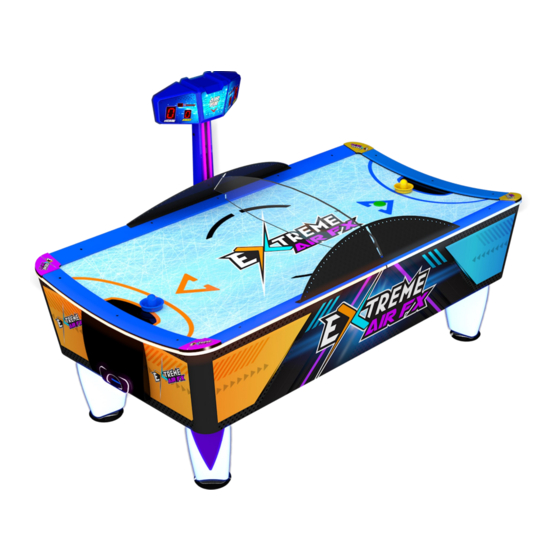
- Page 1 Service Manual Innovative Concepts In Entertainment 10123 Main street, Clarence, NY 14031 WWW.ICEGAME.COM (716) 759-0360 Monday through Friday 8:30am to 6:00pm Eastern Standard...
-
Page 2: Table Of Contents
Table of Contents Safety and warnings ULC wiring Maintenance Assembly 6 - 10 Programming 11 - 13 Accessing collection Free Play mode Test Mode Error messages Warranty Rev B 2-16-2021... -
Page 3: Safety And Warnings
Children should be supervised to ensure that they do not play with the appliance. When replacing the battery, use only authorized parts from ICE. Warranty will be void if non-complaint battery is used. -
Page 4: Ulc Wiring
Universal Card link Connection See Wiring Insert for wire colors and which connections are used. Pin 1. +12v- Supply to Card System = Minimum of 2A available for the card systems and a Max of 3A. Pin 2. Coin 1 - input to the game PCB. Pin 3. -
Page 5: Maintenance
Maintenance Instructions Only qualified personal should preform any maintenance or repairs on this equipment. The playing surface should be cleaned once a day with the air motor running for optimum movement of the puck. Cleaning should be preformed by using any standard household cleaner that is non-abrasive and contains no alcohol. - Page 6 Locate keys and Open The keys are either located in the coin return of the coin door or screwed to the bottom of the cabinet. There should be two different types of keys. One set for the coin door and another to open the player’s puck doors. Locate the legs and feet.
-
Page 7: Assembly
Leg Assembly: After removing the legs from the cabinet, remove the bolt using a 6mm Allen wrench on each leg. You will have to also use a wrench to hold the adjustment rod from spinning out. Then place one feet per leg and reattach the 6mm bolt. - Page 8 Positioning the Table: Flip the table onto its legs using at least four people on either side. Opening The cabinet Top: To unlatch the top, open both puck doors and coin door. Reach into the cabinet and locate the cabinet locks and unlatch them.
- Page 9 Locating the Score Head and sides: The score head assembly is bolted to the bottom of the cabinet. The side rails and divider are attached with straps stapled to the bottom of the cabinet. Installing Score Head: The score head is mounted on the opposite side of the coin door. Insert the wire harness from the score header marquee into the cabinet.
- Page 10 Attaching Side Guards: Using four AA6032 8x1/2 Hex w/tek screws attach the side guards. Slide the playfield divider into the side guard slot. Slide the other side guard into the other end of the playfield divider and attach using AA6032 8x1/2 Hex w/tek screws...
-
Page 11: Programming
How to Enter programming, navigate, and change options. When the game is not in game mode (Score displays shows 0’s), press PB3 and hold until the display is lit. To scroll through the options press either the PB2 or PB3 buttons. To change the value of that option press either PB1 or PB4. To exit programming, press the PB2 button until the display turns off. - Page 12 Line Option = Explanation Minimum & Default T1 = 0 Ticket dispenser enable 0 thru 2 T2 = 1 Number of tickets given per goal when tickets are enabled 0 thru 9 T3 = 0 Number tickets given per game won if tickets are enabled 0 thru 9 T4 = 1 When to pay tickets...
- Page 13 Line Option = Explanation Minimum & Default Event 7 (new coin) tune: Moneda.mp3 V0 = 2 General volume of the music 0 thru 20 V1 = 2 Volume of the music for event 1 (attract mode) 0 thru 20 V2 = 2 Volume of the music for event 2 (standby mode) 0 thru 20 V3 = 2...
- Page 14 TO ACCESS THE COLLECTION DATA • Press PB2 when game is in attract mode. • Pressing PB2 again will cycle through the audits H XXX NUMBER OF BIG COINS COLLECTED L XXX NUMBER OF SMALL COINS COLLECTED E XXX NUMBER OF COINS AT THE ELECTRONIC COIN ACCEPTOR T1 XX NUMBER OF TICKETS DISPENSED T2 XX...
-
Page 15: Error Messages
ERROR MESSAGES: ER01 = Configuration file not found. ER03 = Score PCB’s not connected. ER04 = Battery is low or weak connection. ER05 = Battery is not connected. ER06 = No communication with Dimmer LED boards. How to factory reset the main board: There is a backup memory of the settings from the factory. -
Page 16: Warranty
I.C.E. Inc, at the customer’s expense, within 30 days. After 30 days a 15% re-stocking fee will ap- ply to all returns. ICE distributors are independent, privately owned and operated. In their judgment, they may sell parts and/or accessories other than those manufactured by I.C.E. Inc. We cannot be responsible for the quality, suitability or safety of any non-I.C.E.
Need help?
Do you have a question about the EXTREME AIR FX and is the answer not in the manual?
Questions and answers