Advertisement
Quick Links
Overview
The NXI NetLinx Integrated Controller (FG2101) represents the new generation of
AMX multi-port central controllers. The NXI can be programmed to control
RS-232/422/485, Relay, IR/Serial, and Input/Output devices using the NetLinx
programming language and NetLinx Studio program. For detailed product information,
refer to the NXI NetLinx Integrated Controller Instruction Manual on the
www.amx.com website.
For use as a master controller, the NXI accepts the NXC-ME260 NetLinx Master Card
(FG2010-60).
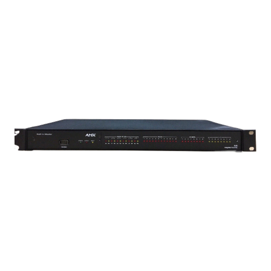
NXI Front Panel Components
FIG. 1 shows the front panel components of the NXI:
I/O LEDs (yellow)
IR/Serial LEDs (red)
Relay LEDs (red)
RS-232/422/485 TX/RX LEDs
(red and yellow)
Master/Hub Card slot
FIG. 1
NXI - Front Panel Components
NXI Rear Panel Components
FIG. 2 shows the rear panel components of the NXI:
ICSP LED (green)
Relays (port 7)
IR/Serial (ports 8-15)
I/O (port 16)
ID Pushbutton
FIG. 2
NXI - Rear Panel Components
Specifications
NXI Specifications
Dimensions (HWD):
1.72" x 17.0" x 8.80"
(43.68 mm x 431.80 mm x 223.52 mm)
Weight:
4.10 lbs (1.85 kg)
Power Requirement:
1.09 A @ 12 VDC (NXI only/no card)
Memory:
64K of IR memory:·
• 32K IR memory for IR ports 8-11
• 32K IR memory for IR ports 12-15
Port Assignments:
• Ports 1-6 = RS-232/422/485 Ports
• Port 7 = 12 Relays
• Ports 8-15 = IR/IR Serial Ports
• Port 16 = 8 I/O Channels
Front Panel Components:
Master/Hub Card slot:
Accepts an NXC-ME260 or Hub Card.
RS-232/422/485
6 sets of red and yellow LEDs light to indicate ports 1-6
TX/RX LEDs:
are transmitting or receiving RS-232, 422, or 485 data:
TX LEDs (red) blink when transmitting data.
RX LEDs (yellow) blink when receiving data.
Relay LEDs:
12 red LEDs light to indicate relay channels 1-12 are
active (closed).
IR/Serial LEDs:
8 red LEDs light to indicate IR/Serial channels 1-8 are
transmitting control data.
I/O LEDs:
8 yellow LEDs light when I/O channels 1-8 are active.
Rear Panel Components:
ID Pushbutton:
Sets the D:P:S assignment for the NXI.
ICSP LED:
Green LED Blinks in unison with the Master card's
NetLinx LED indicating the ICSP bus is synchronized.
This LED flashes rapidly when the NXI is in ID Mode
(see Using the ID Button for details).
RS-232/422/485 (ports 1-6)
Master/Hub Card slot
NXI
NetLinx
NXI Specifications (Cont.)
RS-232/422/485 Ports
6 RS-232/422/485 control ports with XON/XOFF (trans-
(#1-6):
mit on/ transmit off), and CTS/RTS (clear to send/ready
to send), 300-230,400 baud.·
• Channel range = 1-255
• Channels 1-254 provide feedback only.
• Channel 255 (CTS Push channel) reflects the state of
the CTS Input if a 'CTSPSH' command was sent to
the port.
Relays Port (# 7):
12-channel relay port. Channel range = 1-12
You can connect up to 12 independent external relay
devices to the Relay connectors on the NXI (port 7).
Connectors labeled A are for common and B are for
Output.
Each relay is isolated and normally open.
IR/Serial Ports (# 8-15):
8 IR/Serial control ports that support high-frequency
carriers up to 1.14 MHz:
• Channel range = 1-32,000
• Channels 1-253 (output): IR commands.
• Channel 254 (feedback): PowerFail (used with 'PON'
and 'POF' commands).
• Channel 255 (feedback): Power status (when IOLink
is set).
I/O Port (# 16):
8-channel I/O port for contact closure, 0-5 VDC voltage
sensing, or interactive power sensing for IR ports.
Channel range = 1-8.
Master/Hub Card Slot
The Master/Hub Card slot houses a NetLinx Master or Hub Card. The card mounts in
a horizontal position, through the master card slot on the rear panel of the NXI
enclosure. To install a Master or Hub Card in an NXI:
Discharge the static electricity from your body by touching a grounded object.
1.
Disconnect the power, and unplug all connectors from the NXI.
2.
Align the edges of the card with the guide slots inside the Master Card slot on
3.
the NXI.
Slide the card about halfway into the slot.
4.
Inside the Master Card slot, locate the 4-pin control cable connector.
5.
Plug the connector from the NXI into the 4-pin terminal on the Master Card. This
6.
connector is keyed to ensure correct orientation.
Once the control cable is connected, gently slide the card all the way in until you
7.
feel the rear edge of the card lightly snap into place.
Re-apply power and other connections as necessary.
8.
Compatible NetLinx Hub Cards
For use as a hub device, the NXI accepts the following NetLinx Hub Cards:
•
NXC-NH ICSNet Hub Card (FG2060)
•
NXC-HS ICSHub Server Card (FG2061)
•
NXC-HE ICSHub Expander Card (FG2062)
Connections and Wiring
RS-232/422/485 Wiring Specifications:
RS-232/422/485 Wiring Specifications
Pin
Signal
Function
1
GND
Signal ground
2
RXD
Receive data
3
TXD
Transmit data
4
CTS
Clear to send
5
RTS
Request to send X
6
TX +
Transmit data
7
TX -
Transmit data
8
RX +
Receive data
9
RX -
Receive data
10
12 VDC
Relay Wiring Specifications
You can connect up to 12 independent external relay devices to the Relay connectors
on the NXI (port 7).
•
Connectors labeled A are for common and B are for Output.
•
Each relay is isolated and normally open.
•
A metal commoning strip is supplied with each NXI to connect multiple relays.
Installation Guide
Integrated Controller
®
RS-232
RS-422
RS-485
X
X
X
X
X
X
X (strap to pin 8)
X
X (strap to pin 9)
X
X (strap to pin 6)
X
X (strap to pin 7)
optional
optional
Advertisement

Related Manuals for AMX NXI


Summary of Contents for AMX NXI
-
Page 1: Nxi Netlinx Integrated Controller
The Master/Hub Card slot houses a NetLinx Master or Hub Card. The card mounts in Master/Hub Card slot a horizontal position, through the master card slot on the rear panel of the NXI enclosure. To install a Master or Hub Card in an NXI: Discharge the static electricity from your body by touching a grounded object. -
Page 2: Using The Id Button
12 VDC PWR Using the ID Button The ID Button on the rear panel of the NXI (see Figure 1) is used in conjunction with the NetLinx Studio software program to allow you to assign a new Device number to the NXI.