
Related Manuals for AMX NetLinx Integrated Controllers NI-700/900


Summary of Contents for AMX NetLinx Integrated Controllers NI-700/900
- Page 1 Hardware Reference Guide NI-700/900 NetLinx Integrated Controllers N e t L i n x I n t e g r a t e d C o n t r o l l e r s L a s t R e v i s e d : 5 / 1 3 / 2 0 0 8...
- Page 2 AMX is not responsible for products returned without a valid RMA number. AMX is not liable for any damages caused by its products or for the failure of its products to perform. This includes any lost profits, lost savings, incidental damages, or consequential damages.
-
Page 3: Table Of Contents
Table of Contents Introduction ...1 NI-700 Overview... 1 NI-700 Specifications ... 1 NI-700 Port Assignment And Functionality ... 4 NI-700 On-Board Memory Specifications ... 4 NI-900 Overview... 5 NI-900 Specifications ... 5 NI-900 Port Assignment And Functionality ... 8 NI-900 On-Board Memory Specifications ... 9 TimeKeeper ... - Page 4 Table of Contents NI-700 & NI-900 Hardware Reference Guide...
-
Page 5: Introduction
• 1 RS-232 Program port • 2 RS-232/RS-422/RS-485 ports • 1 IR/Serial Output ports • 4 Digital Input/Output ports • 1 IR RX (receive) port (works only with AMX IR Receivers) IR LED (red) I/O LEDs (yellow) Serial RS-232/422/485 TX/RX LEDs (red/yellow) - Page 6 Introduction NI-700 Specifications Dimensions (HWD): Power Requirements: Memory: Microprocessor: Weight: Enclosure: Certifications: Front Panel Components: Program port Configuration DIP switch • Sets the communication parameters for the Program port. IR RX LED IR LED I/O LEDs Serial LEDs LINK/ACT Status Output Input ID pushbutton...
- Page 7 • 4-pin 3.5 mm mini-Phoenix port is used to connect one or more (8 maximum) IRX-SM+ swivel mount or IRX-DM+ Decora mount IR receivers. • The IR RX port functions using AMX IR codes (38 KHz and 455 KHz) and works ONLY with AMX IR Receivers such as the IRX-DM+ and IRX-SM+.
-
Page 8: Ni-700 Port Assignment And Functionality
Introduction NI-700 Specifications (Cont.) Operating Environment: Included Accessories: Other AMX Equipment: NI-700 Port Assignment And Functionality NI-700 Port Assignments Port Serial Port #1 Serial Port #2 IR Port I/O Port IR RX Port NI-700 On-Board Memory Specifications There are two variations on the NI-700, with different memory specifications. The latest version of the NI-700 has double the on-board memory of previous versions. -
Page 9: Ni-900 Overview
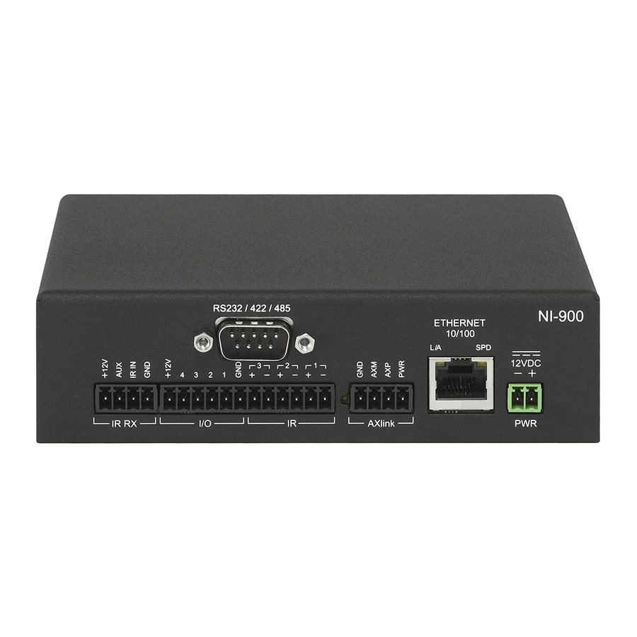
NI-900 Overview The NI-900 is the first NetLinx device to be Duet-compatible straight out of the box. Duet is a dual-interpreter firmware platform from AMX which combines the proven reliability and power of NetLinx with the extensive capabilities of the Java... - Page 10 Introduction NI-900 Specifications Dimensions (HWD): Power Requirements: Memory: Microprocessor: Weight: Enclosure: Certifications: Front Panel Components: Program port Configuration DIP switch IR RX LED IR LEDs I/O LEDs Serial LEDs LINK/ACT Status Output Input ID pushbutton Rear Panel Components: RS-232/422/485 (Port 1) •...
- Page 11 (8 maximum) IRX-SM+ swivel mount or IRX-DM+ Decora mount IR receivers. • The IR RX port functions using AMX IR codes (38 KHz and 455 KHz) and works ONLY with AMX IR Receivers such as the IRX-DM+ and IRX-SM+. • Four-channel binary I/O port for contact closure with each input being capable of voltage sensing.
-
Page 12: Ni-900 Port Assignment And Functionality
NI-900 Specifications (Cont.) Rear Panel Components (Cont.): Ethernet Link/ Activity LED Power port Operating Environment: Included Accessories: Other AMX Equipment: NI-900 Port Assignment And Functionality NI-900 Port Assignments Port Serial Port #1 IR/Serial Port #1 IR/Serial Port #2 IR/Serial Port #3... -
Page 13: Ni-900 On-Board Memory Specifications
For information on using the on-board Web Console, as well as NetLinx send commands and terminal communications to configure the NI Controllers, refer to the NetLinx Integrated Controller WebConsole & Programming Guide. All product documentation is available to view or download from www.amx.com. NI-700 & NI-900 Hardware Reference Guide Introduction... - Page 14 Introduction NI-700 & NI-900 Hardware Reference Guide...
-
Page 15: Installation
Installation Device:Port:System (D:P:S) A device is any hardware component that can be connected to an AXlink or ICSNet bus. Each device must be assigned a unique number to locate that device on the bus. The NetLinx programming language allows numbers in the range 1-32,767 for ICSNet (255 for AXlink). Only the Device value can be set through the DIP switch settings mentioned above. - Page 16 Installation To prevent repetition of the installation, test the incoming wiring by connecting the Controller’s connectors to their terminal locations and applying power. Verify that the unit is receiving power and functioning properly. Disconnect the terminal end of the power cable from the connected 12 VDC-compliant power supply. 6.
-
Page 17: Connections And Wiring
Connections and Wiring Setting the Configuration DIP Switch (for the Program Port) Prior to installing the Controller, use the Configuration DIP switch to set the baud rate used by the Program port for communication. The Configuration DIP switch is located on the front of the Integrated Controllers. -
Page 18: Working With The Configuration Dip Switch
Connections and Wiring Think of the PRD Mode (On) equating to a PC’s SAFE Mode setting. This mode allows a user to continue powering a unit, update the firmware, and download a new program while circumventing any problems with a currently downloaded program. Power must be cycled to the unit after activating/deactivating this mode on the Program Port DIP switch #1. -
Page 19: Modes And Front Panel Led Blink Patterns
Both the NI-700 and NI-900 have an AXlink port and adjacent status LED (FIG. 1). This port allows the NI to support AMX Legacy AXlink devices such as G3 touch panels (ex: CP4/A) and PosiTrack Pilot devices. A green LED shows AXlink data activity. When the AXlink port is operating normally, blink... -
Page 20: Wiring Guidelines
Connections and Wiring NI-700 FIG. 1 AXlink connector and LED The AXlink port can be used to supply power to downstream AXlink-compatible devices as long as both the power required is LESS THAN 2 Amps total and the external power supply feeding the NI unit has the necessary power capability. -
Page 21: Wiring A Power Connection
Wiring A Power Connection To use the 2-pin 3.5 mm mini-Phoenix connector with a 12 VDC-compliant power supply, the incoming PWR and GND cables from the external source must be connected to their corresponding locations on connector (FIG. 2). 1. Insert the PWR and GND wires on the terminal end of the 2-pin 3.5 mm mini-Phoenix cable. Match the wiring locations of the +/- on both the power supply and the terminal connector. -
Page 22: Using The 4-Pin Mini-Phoenix Connector For Data With External Power
Connections and Wiring Using the 4-pin Mini-Phoenix Connector For Data With External Power To use the 4-pin 3.5 mm mini-Phoenix (female) captive-wire connector for data communication and power transfer, the incoming PWR and GND cable from the 12 VDC-compliant power supply must be connected to the AXlink cable connector going to the Integrated Controller. -
Page 23: Irx-Rx Port: Connection And Wiring
The NI-700 and NI-900 units both have a single rear 4-pin IR receiver port (IR RX). The IR RX port functions using AMX IR codes (38 KHz and 455 KHz) and works ONLY with AMX IR Receivers such as the IRX-DM+ and IRX-SM+. -
Page 24: Input/Output (I/O) Port: Connections And Wiring
Connections and Wiring Input/Output (I/O) Port: Connections and Wiring The I/O port responds to either switch closures, voltage level (high/low) changes, or it can be used for logic-level outputs. You can connect up to four devices to the NI-700 or NI-900 (FIG. 7). FIG. -
Page 25: Ir/Serial Port: Connections And Wiring
IR/Serial Port: Connections and Wiring You can connect only one IR- or Serial-controllable device to the IR/Serial connectors on the rear of the NI-700 (FIG. 8) but you can connect up to three IR- or Serial-controllable devices to the rear of the NI-900. -
Page 26: Ethernet Leds
Connections and Wiring FIG. 9 diagrams the RJ-45 pinouts and signals for the Ethernet RJ-45 connector and cable. FIG. 9 RJ-45 wiring diagram Ethernet LEDs L/A - Link/Activity LED lights (green) when the Ethernet cables are connected and terminated correctly. FIG. -
Page 27: Ethernet Ports Used By The Integrated Controller
1319, or disable ICSP over Ethernet completely from either Telnet or the Program Port located on the rear of the Master itself. This type of communication is used by the various AMX product for communication amongst themselves. integration! - Page 28 Connections and Wiring NI-700 & NI-900 Hardware Reference Guide...
- Page 29 Connections and Wiring NI-700 & NI-900 Hardware Reference Guide...
- Page 30 It’s Your World - Take Control™ 3000 RESEARCH DRIVE, RICHARDSON, TX 75082 USA • 800.222.0193 • 469.624.8000 • 469-624-7153 fax • 800.932.6993 technical support • www.amx.com...
Need help?
Do you have a question about the NetLinx Integrated Controllers NI-700/900 and is the answer not in the manual?
Questions and answers