
Related Manuals for DMT 320A


Summary of Contents for DMT 320A
- Page 1 U S E R G U I D E , VO L . 2 . 1 S I N G L E W I R E M YO G R A P H S Y S T E M - 3 2 0 A...
- Page 2 SINGLE WIRE MYOGRAPH - 320A USER GUIDE...
-
Page 3: Table Of Contents
CONTENTS Chapter 1 - Single Wire Myograph overview ..................................3 Chapter 2 - Setting up the Single Wire Myograph ................................4 2.1 Adjustment of supports ..................................4 2.2 Force transducer calibration ................................5 Chapter 3 - Experimental set-up ......................................6 3.1 Mounting protocol for small arteries ..............................6 3.1.1 Mounting step one ..................................6 3.1.2 Mounting step two ..................................7 3.1.3 Mounting step three ...................................7... -
Page 4: Chapter 1 - Single Wire Myograph Overview
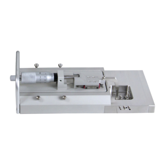
CHAPTER 1 - SINGLE WIRE MYOGRAPH OVERVIEW Port for connection to Wire Interface Transducer house Allen screws for fine alignment of the jaws Micrometer (2 on each side) Pipe for gas supply Pipe for filling the chamber (using the 40 mm funnel) Suction pipe for connection to vacuum pump Force transducer pin... -
Page 5: Chapter 2 - Setting Up The Single Wire Myograph
PLACED DIAGONALLY TO THE ALLEN SCREW BEING TIGHTENED, OTHERWISE THERE IS A HIGH RISK OF DAMAGING THE SINGLE WIRE MYOGRAPH FRAME. Figure 2.1 Illustration of screws for adjusting supports and horizontal adjustment SINGLE WIRE MYOGRAPH SYSTEM - 320A - USER GUIDE... -
Page 6: Force Transducer Calibration
2.2 Force transducer calibration DMT recommends that the Single Wire Myograph is force calibrated at least once every month. DMT also recommends that the Single Wire Myograph is force calibrated every time the system has been moved or has not been used for a long period of time. -
Page 7: Chapter 3 - Experimental Set-Up
(figure 3.1 B-C). • Fill the Single Wire Myograph chamber with PSS (at room temperature). See appendix 1 for example of buffer recipes. Figure 3.1 A, B and C Mounting step 1 SINGLE WIRE MYOGRAPH SYSTEM - 320A - USER GUIDE... -
Page 8: Mounting Step Two
3.1.2 Mounting step two • Using forceps to hold the handle segment, transfer excised vessel from Petri dish to Single Wire Myograph chamber. Hold the vessel as close to the proximal end as possible and try to mount the vessel onto the wire. •... -
Page 9: Mounting Step Four
Once the wire has successfully passed through the lumen of the vessel segment, place the wire in a position, which ensures sufficient length for the wire to be secured both at the near and far fixing screws on the right-hand jaw. Figure 3.5 A, B and C Mounting step 5 SINGLE WIRE MYOGRAPH SYSTEM - 320A - USER GUIDE... -
Page 10: Mounting Step Six
3.1.6 Mounting step six • Carefully move the jaws together while ensuring that the second mounted wire lies underneath the first one secured on the left-hand jaw (figure 3.6 A). The procedure clamps the second wire to prevent it from damaging the vessel segment when securing the wire to the right-hand jaw (connected to the transducer). -
Page 11: Principles Of The Normalization Procedure
The final stimulus is performed using a mixture of PSS and 10 μM noradrenaline. All solutions are preheated to 37 C and aerated with a mixture of 95% O and 5% CO before use. Instructions for making the necessary solutions are described in appendix 1. SINGLE WIRE MYOGRAPH SYSTEM - 320A - USER GUIDE... -
Page 12: Endothelium Function
Repeat 1 x -- Wash out -- -- Stimulus 1 & 2 -- 4 x with PSS KPSS + 10 μM NA Wait 5 minutes Stimulate for 3 minutes -- Stimulus 3 -- -- Wash out -- PSS + 10 μM NA 4 x with PSS Stimulate for 3 minutes Wait 5 minutes... -
Page 13: In Vitro Experiment 1: Noradrenaline Contractile Response
1 μL of 10 7.5 μL of 10 1 μL of 10 2.5 μL of 10 *In calculating the [NA] in the Single Wire Myograph chamber, the applied volume of noradrenaline is ignored. SINGLE WIRE MYOGRAPH SYSTEM - 320A - USER GUIDE... -
Page 14: In Vitro Experiment 2: Acetylcholine Relaxation Curve
3.6 In vitro experiment 2: Acetylcholine relaxation curve The purpose of the present protocol is to determine the sensitivity of the endothelium dependent vasodilator acetylcholine in noradrenaline pre-contracted rat mesenteric small arteries. 3.6.1 Background Acetylcholine causes relaxation of rat mesenteric small arteries by activating of muscarinic M3 receptors at the endothelial cell layer leading to release of endothelium-derived relaxing factors. -
Page 15: Chapter 4 - Cleaning And Maintenance
As a part of the general maintenance of the Single Wire Myograph, DMT recommends that the Single Wire Myograph is force calibrated at least once a month. The Single Wire Myograph should also be force calibrated every time the Wire Interface has been moved. -
Page 16: Maintenance Of The Force Transducer
DMT RECOMMENDS USE OF THE HIGH VACUUM GREASE ONCE A WEEK TO SEAL THE TRANSDUCER HOLE BY FREQUENTLY USE. DMT TAKES NO RESPONSIBILITIES FOR THE USE OF ANY OTHER KINDS OF HIGH VACUUM GREASE THAN THE ONE TO BE PURCHASED FROM DMT. -
Page 17: Force Transducer Replacement
11. Mount the support on the transducer pin and adjust the supports as described in chapter 2.1. IMPORTANT BEFORE MAKING ANY EXPERIMENT ON THE SINGLE WIRE MYOGRAPH, REMEMBER TO PERFORM A NEW FORCE CALIBRATION. SINGLE WIRE MYOGRAPH SYSTEM - 320A - USER GUIDE... -
Page 18: Maintenhance Of The Linear Slide
4.3 Changing the Single Wire Myograph window glass The glass in the Single Wire Myograph chamber window is fixed in place and kept waterproof by a thin layer of high vacuum grease on the circular edge between the glass and the chamber base. The following procedure describes how to change the window glass: 1. -
Page 19: Appendix 1 - Buffer Recipes
29.25 3.625 7.25 14.5 29.0 NaHCO (84.01) 622.50 26.25 52.50 104.50 209.25 Glucose (180.16) 137.50 12.50 25.00 50.00 100.00 EDTA (380) 0.65 0.125 0.25 0.50 CaCl (110.99) 20mL 40mL 80mL 160mL SINGLE WIRE MYOGRAPH SYSTEM - 320A - USER GUIDE... - Page 20 1. Make a 1.0M solution of CaCl (110.99) in double-distilled H O. Filter-sterilize the calcium solution through a 0.22 μm filter. The sterilized solution can be stored in the refrigerator for up to 3 months. 2. Dissolve all the chemicals except the NaHCO3, Glucose, and CaCL2, in approximately 80% of the desired final volume of double distilled H O while being constantly stirred.
-
Page 21: Appendix 2 - Normalization Theory
, by a factor k. The factor is for rat mesenteric arteries 0.9. Again, this value should be optimized for the particular tissue preparation being used by a length-tension curve. = k •IC SINGLE WIRE MYOGRAPH SYSTEM - 320A - USER GUIDE... - Page 22 The normalized internal (lumen) diameter is then calculated by: The micrometer reading X at which the internal circumference of the normalized vessel is set to is calculated by: – IC APPENDIX 2...
-
Page 23: Appendix 3 - Reading A Millimetre Micrometer
3. Read the value on the thimble corresponding to the intersection with the horizontal line on the sleeve. A. Reading on sleeve: 16000 µm B. One additional mark visible: 500 µm C. Thimble reading: 280 µm Total reading: 16780 µm Figure A2.3 Example 2: reading = 16780 µm SINGLE WIRE MYOGRAPH SYSTEM - 320A - USER GUIDE... -
Page 24: Notes
NOTES NOTES...
Need help?
Do you have a question about the 320A and is the answer not in the manual?
Questions and answers