Table of Contents
Advertisement
Quick Links
related literature |
SRP-003-794, Pretium EDGE
SRP-006-136, Multifiber Connector and Port Cleaning with the TKT-CLEAN-MFC-M kit
table of contents |
1. General .................................................................................................................................................1
2. Precautions ...........................................................................................................................................2
3. Tools and Materials ...............................................................................................................................2
4. Connector and Adapter Cleaning ..........................................................................................................2
5. Calculating System Loss .Budgets .......................................................................................................3
6. The Functionality of the Tap Module Splitters .......................................................................................5
7. Installing Pretium EDGE Tap Modules ...................................................................................................6
8. Referencing the Test Equipment for a Tap Module ...............................................................................6
9. Testing Pretium EDGETap Modules .....................................................................................................8
1.
General
1.1
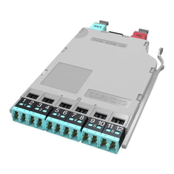
This procedure describes Pretium EDGE
Tap Modules, which are available for both multimode
and single mode applications. Compatible with all
Pretium EDGE rack-mountable connector housings,
TAP modules have twelve front-mounted shuttered
LC adapters and two MTP
(Figure 1).
1.2
The module contains 12 fiber optic splitters which divide the incoming optical signals into two
outputs, one for live link traffic and one for monitoring. The monitor traffic is routed via the "TAP"-labeled
MTP connector to a monitoring device which filters the data and sends it to various software tools for
analysis, where it is then viewed in application-layer software for security threats, performance issues, or
system optimization.
IMPORTANT: Please note that Tap module systems have two outputs for each input, which may
require two power meters, and depending on the system configuration, possibly require an additional
craftsperson in another location.
1.4
If this procedure is reissued, a summary of the changes will appear in this paragraph.
STANDARD RECOMMENDED PROCEDURE 003-126 | ISSUE 1 | OCTOBER 2012| PAGE 1 OF 9
Solution
®
connectors in back
®
Pretium EDGE
Installation and Testing
SRP 003-126, Issue 1
HPA-0753
Tap Module
®
Figure 1
Advertisement
Table of Contents

Subscribe to Our Youtube Channel
Related Manuals for CORNING Pretium EDGE ETM-7B-G


Summary of Contents for CORNING Pretium EDGE ETM-7B-G
-
Page 1: Table Of Contents
Pretium EDGE Tap Module ® Installation and Testing SRP 003-126, Issue 1 related literature | SRP-003-794, Pretium EDGE Solution ® SRP-006-136, Multifiber Connector and Port Cleaning with the TKT-CLEAN-MFC-M kit table of contents | 1. General ..............................1 2. Precautions ............................2 3. Tools and Materials ..........................2 4. Connector and Adapter Cleaning ......................2 5. -
Page 2: Precautions
Precautions Laser Precautions \WARNING: DO NOT use magnifiers in the presence of laser light - diffused laser light can cause eye damage of focused with optical instruments. Never look directly into the end of a connector that may be carrying laser light. Should accidental eye exposure to laser light be suspected, arrange for an eye examination immediately Cable Handling Precautions NOTE: Fiber optic cable is sensitive to excessive pulling, bending, and crushing forces. Do not bend cables more sharply than their minimum recommended bend radius. -
Page 3: Calculating System Loss Budgets
Calculating System Loss Budgets This section describes how to calculate the loss budgets of a system using a Pretium EDGE Tap Module. Note that you will need to calculate one loss budget for the LIVE system (Figure 4) and two different loss budgets for the Tap output (Figure 5 and 6). Table 1 indicates the system loss values of the system components: Multimode Fiber Single Mode Fiber Bend-improved... - Page 4 Budget loss for a “Near end” Tap port test harness multimode system using OM4 fiber and 50 /50 splitters: 0.15 +3.8 + 0.35 + 0.15 = 4.45 dB + fiber loss LC mated 50/50 pair splitter 0.15 mated pair 0.35 Note: Fiber loss depends on length of system...
-
Page 5: The Functionality Of The Tap Module Splitters
The Functionality of the Tap Module Splitters Directionality 6.1 In simplest terms, the splitters inside a Tap module act like a divider of a one-way traffic flow – in this case, light. Input LIVE into The even-numbered LC connectors in a Tap output LC # 2 module serve only for source input and their traffic is split between the LIVE and TAP outputs (Figure 7, Tap Output top). on MTP Fiber 1 Output In the same fashion, the Tap module’s odd- numbered LC connectors receive live traffic from... -
Page 6: Installing Pretium Edge Tap Modules
7. Installing a Pretium EDGE Tap Module 7.1 Pretium EDGE Tap modules are installed just like their normal Pretium EDGE module counterparts. Refer to the Installation chapter in SRP-003-794, Pretium EDGE Solution, for complete instructions. This procedure covers module installation, trouble shooting, and other module-related topics as well. Install the Tap module and its Tap MTP harness into your system housing (this procedure illustrates an MTP to LC harness). - Page 7 Step 6: Clean and install an LC to LC jumper- multimode only Reference Jumper no. 2 (RJ2) into M1 and the LC adapter (Figure 9). adapter Reference Step 7: Verify that the RJ1/ RJ2 mated pair are Jumper no. 2 acceptable with a loss ≤0.15 dB. Do NOT Do NOT 0.15 dB disconnect disconnect Step 8: Disconnect RJ2’s LC connector from the LC adapter and protect it with a clean Light dust cap until you are ready to start the...
-
Page 8: Testing Pretium Edgetap Modules
Testing Pretium EDGE Tap Modules Table 2 provides a complete guide to the testing sequence for testing with the light source at the Tap module “A” (“Near end”) and a meter at Module “B”, or the “Far end” of the system shown in Figure 11. Source LC Position at “A' Module “B” LC Position Meter no. 2 -TAP Port Test Harness A-10 A-12 B-11... - Page 9 1-800-743-2671 • FAX +1-828-325-5060 • International +1-828-901-5000 • http://www.corning.com/cablesystems Corning Cable Systems reserves the right to improve, enhance, and modify the features and specifications of Corning Cable Systems’ products without prior notification. Pretium EDGE is a registered trademark of Corning Cable Systems Brands, Inc. MTP is a registered trademark of USConec, Ltd. All other trademarks are the properties of their respective owners. Corning Cable Systems is ISO 9001 certified. ©2012 Corning Cable Systems. All rights reserved. Published in the USA.
Need help?
Do you have a question about the Pretium EDGE ETM-7B-G and is the answer not in the manual?
Questions and answers