Advertisement
Quick Links
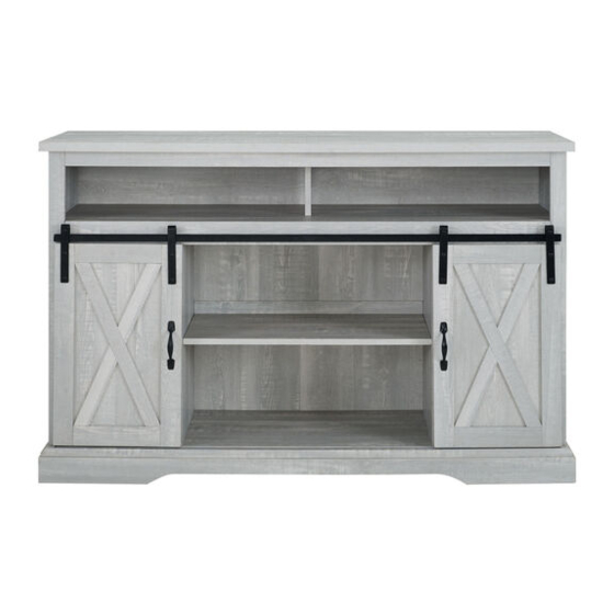
Item# : W52HBSBD
Assembly Instructions
t
Please visit our website for the most current instroctions, assembly
悦report damage,
or request parts. www.walkeredison.com
Revised 12/09/2018
。
。
c
P.1
pyright © 2018, by Walker Edis
n Furniture C
LLC. All rights
served.
缸,
陪
Advertisement

Related Manuals for Walker Edison W52HBSBD


Summary of Contents for Walker Edison W52HBSBD
- Page 1 Item# : W52HBSBD Assembly Instructions Please visit our website for the most current instroctions, assembly 悦report damage, or request parts. www.walkeredison.com Revised 12/09/2018 。 。 pyright © 2018, by Walker Edis n Furniture C LLC. All rights served. 缸, 陪...
- Page 4 Plastic strap Glue tube Philips head screwdriver required for assembly (not included) The hardware quantities listed above are required for proper assembly. Some extra hardware may also have been included. Copyright 2018, by Walker Edison Furniture Co., LLC. All rights reserved.
- Page 5 Step 1 。 扩 ' 。 � 叭 〉 飞~ 〉 〈 。 飞 〉 Attach cam bolt (B) to part (24,8) with screwdriver. Insert Dowel (A) into part (9). 。 。 pyright © 2018, by Walker Edis n Furniture C LLC.
- Page 6 Insert wooden dowel (A) into part (4,5). Attach cam bolt (B) to part (4,5) with screwdriver...
- Page 7 Attach part (8,24) to part (4,5), then insert and secure cam lock (C) to part (4,5) to lock it.
- Page 8 Insert wooden dowel (A) into part (6,7).
- Page 9 Insert wooden dowel (A) into part (11). Attach cam bolt (B) to part (1) with screwdriver.
- Page 10 Attach part (11) to part (1) by using screw (L) with screwdriver.
- Page 11 Attach cam bolt (B) to part (12,3) with screwdriver. Insert wooden dowel (A) into part (3).
- Page 12 Attach part (3) to part (12), then insert and secure cam lock (C) to part (3) to lock it.
- Page 13 Attach part (9) to part (3) using bolt (F) with hex key (G).
- Page 14 Attach part (5,24) to part (3,12) then insert and secure cam lock (C) in part (3,12) to lock it.
- Page 15 Attach part (4,8) to part (3,12) then insert and secure cam lock (C) in part (3,12) to lock it...
- Page 16 Slide back panel (10) into grooves as per diagram.
- Page 17 Attach part 1 to part (4,5,9) then insert and secure cam lock (C) to part (4,5,9) to lock it.
- Page 18 Attach part (6) to part (3) using cam lock (C) to secure.
- Page 19 Attach part (7) to part (3), then insert and secure cam lock (C) to part (7) to lock it.
- Page 20 Slide back panel (16,17) into grooves as per diagram.
- Page 21 Attach part (13) to part (17)
- Page 22 Attach part (23) to part (13)
- Page 23 Attach part (2) to part (4,6,7,5) using Screw (F) with hex key (G).
- Page 24 Attach connector (R) to part (22,20,21) using bolt (E) with hex key (G).
- Page 25 Attach part (20) to part (21) using bolt (E) with hex key (G).
- Page 26 Attach part (22) to part (21) using bolt (E) with hex key (G).
- Page 27 Attach Base unit (20,21,22) to part (2) using connector (R) with bolt (E) and hex key (G).
- Page 28 Attach plastic wedge (T) using screw (S) with screwdriver.
- Page 29 Place sticker (D) over holes as per diagram.
- Page 30 Insert shelf support pin (H) into part (4,6,7,5)
- Page 31 Place shelf (14,15) on top of support pin.
- Page 32 Attach pulley (P) using bolt (Q), and plate (N) using screw (M) to part (18)(19) with screwdriver, Using Bolt(K) secure handle (J)
- Page 33 Place door guide (N) on door into the groove on part (2). Then hang pully (P) on part (12). Door should fit securely and glide smoothly. Hang pulley (P) to part (12) then press down to hold the door.
- Page 34 Attach plastic strap (V) to back panel by using screw (M) with screwdriver Insert Nut (W) into wall...
- Page 35 Insert screw (...
Need help?
Do you have a question about the W52HBSBD and is the answer not in the manual?
Questions and answers