Advertisement
Quick Links
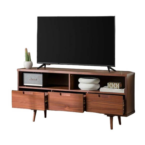
Item #: W52IV3DCRN
Assembly Instruction
Please visit our website for the most current instructions, assembly tips report damage,
or request parts. www.walkeredison.com
Revised 05/2021
Copyright
2018, by Walker Edison Furniture Co., LLC. All rights reserved.
P .1
c
Advertisement

Related Manuals for Walker Edison W52IV3DCRN


Summary of Contents for Walker Edison W52IV3DCRN
- Page 1 Item #: W52IV3DCRN Assembly Instruction Please visit our website for the most current instructions, assembly tips report damage, or request parts. www.walkeredison.com Revised 05/2021 Copyright 2018, by Walker Edison Furniture Co., LLC. All rights reserved. P .1...
- Page 3 (3x) Part# Description Part# Description Top panel 01 pcs Upper back panel 01 pcs Shelf 01 pcs Back panel 01 pcs Base 01 pcs Drawer front 03 pcs Center upper panel 01 pcs Drawer left side 03 pcs Center bottom panel 02 pcs Drawer right side 03 pcs...
- Page 4 5,5x28mm Cam Bolt 10 pcs 14x14mm Cam Lock 10 pcs 3,5x3 mm 46 pcs 8,0x30 mm 54 pcs 3,5x16 mm 28 pcs Plastic Slide 06 pcs 4,0x4 mm 14 pcs 07 pcs 3,5x20 mm 08 pcs Drawer Limiter 03 pcs...
- Page 5 Step 1 Insert wooden dowel (D) into part (2), (4), (5), (6), (7), (8), (12), (13) and (16). (2x) (2x) (2x) (3x) (3x) Ø 8,0x30 mm Step 2 Secure Slide (F) to part (6) and (7) with Screw (E). ( x) Ø...
- Page 6 Step 3 Attach the Plastic Slide (F) into part (5) using Screw (I) and a Phillips head screwdriver. Complete this step twice. (180º) (180º) (8x) Ø 3,5x20 mm Step 4 Secure part (2) to part (4) with screw (G). (2x) Ø...
- Page 7 Step 5 Secure parts (5) to part (2) with screw (C). (6x) Ø 3,5x30 mm Step 6 Secure parts (6) and (7) to part part (2) with screw (C). (4x) Ø 3,5x30 mm...
- Page 8 Step 7 Insert screw Cam Bolt (A) into top panel (1). Ø 5,5x28 mm Step 8 Secure parts (8) to part (3) with screw (C). Insert stop (J) to part (3) with screw (E). (12x) ( x) (180º) (03x) Ø 3,5x30 mm Ø...
- Page 9 Step 9 Secure part (3) to parts (5), (6), (7) and (16). Step 10 Attach part (1) in the wood dowels of part (4), (6), (7) and (16) using cam bolt (B) and phillips screw driver (not included). (10x)
- Page 10 Step 11 Secure part (3) with screw (G). (12x) Ø 4,0x40 mm Step 12 Secure back panel (9) and (10) with screw (E) at some points as shown using the hardware (H). (7x) Ø 3,5x16 mm P.10...
- Page 11 Attach part (12) and (13) in the part (11) using screw (C). Step 13 Attach part (14) and (15) as shown using screw (C). Ø 3,5x30 mm Step 14 Assembly Complete! P.11...
Need help?
Do you have a question about the W52IV3DCRN and is the answer not in the manual?
Questions and answers