
Related Manuals for Newport Electronics INFINITY Series


Summary of Contents for Newport Electronics INFINITY Series
- Page 1 ® INFCR and INFCR-xxxB INFINITY ® C Programmable Digital RTD Meter Operator’ s Manual NEWPORT Electronics, Inc.
- Page 2 European New Approach Directives. NEWPORT will add the CE mark to every appropriate device upon certification. The information contained in this document is believed to be correct but NEWPORT Electronics, Inc. accepts no liability for any errors it contains, and reserves the right to alter specifications without notice.
- Page 3 PREFACE Manual Objectives This manual shows you how to set up and use the Programmable Digital RTD Meter. Standard Procedures: Checking voltage jumpers, or changing voltage power Mounting the panel Selecting the input type Selecting a decimal point position Setting the setpoint's active band Selecting a latched or unlatched operation Setting setpoint deadbands Enabling/disabling setpoint changes...
-
Page 4: Table Of Contents
Table of Contents Section Page 1. INTRODUCTION ..........1 1.1 UNPACKING . - Page 5 Table of Contents 4.9 OUTPUT CONFIGURATION (OT.CF) ......23 4.9.1 To Enable or Disable The Analog Output ....23 4.9.2 To Select Analog Output as Current or Voltage .
- Page 6 Table of Contents List of Figures Figure Page Figure 2-1. Front-Panel with “Big” LED Display ......5 Figure 2-2.
- Page 7 Table of Contents NOTES, WARNINGS and CAUTIONS Information that is especially important to note is identified by these labels: • NOTE • WARNING • CAUTION • IMPORTANT NOTE: provides you with information that is important to successfully setup and use Note the Programmable Digital Meter.
- Page 8 vi vi...
-
Page 9: Unpacking
SECTION 1. INTRODUCTION 1.1 UNPACKING Remove the Packing List and verify that all equipment has been received. If there are any questions about the shipment, use the phone numbers listed on the back cover to contact the Customer Service Department nearest you. Upon receipt of shipment, inspect the container and equipment for any signs of damage. -
Page 10: Introduction
Introduction 1.2 SAFETY CONSIDERATIONS This device is marked with the international caution symbol. It is important to read this manual before installing or commissioning this device as it contains important information relating to Safety and EMC (Electromagnetic Compatibility). This instrument is a panel mount device protected in accordance with Class I of EN 61010 (115/230 AC power connections), Class III for the DC Voltage Power Option (10-32 Vdc). -
Page 11: About The Meter
SECTION 2. ABOUT THE METER 2.1 DESCRIPTION The Resistance Temperature Detector (RTD) meter is a value packed indicator/controller. Four full digits accurately display your temperature. Select from 2, 3 or 4 wire input configuration. Your meter may be a basic indicator or it may include analog output or dual relay output. Analog or dual relay output must be ordered at time of purchase. -
Page 12: Available Accessories
About The Meter 2.3 AVAILABLE ACCESSORIES Table 2-1. Accessories and Add-Ons Add-On Options Special Calibration/Configuration SPC4 NEMA-4 Splash Proof Cover SPC18 NEMA-4 Splash Proof Cover, NEW Accessories TP1A Trimplate panel adaptor. Adapts DIN1A/DIN2A cases to larger panel cutouts RP18 19-In. Rack Panel for one (1) 1/8 DIN instrument RP28 19-In. -
Page 13: Front Of The Meter
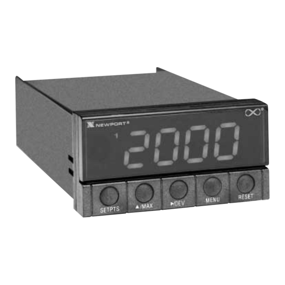
About The Meter 2.4 FRONT OF THE METER Figure 2-1 shows each part of the front of the three-color programmable “Big” LED display meter (Version B). Digital LED Display: -1.9.9.9 or 9.9.9.9 4-digit three color programmable, 21 mm (0.83") high LED display with programmable decimal point. - Page 14 About The Meter 2.4 FRONT OF THE METER (Continued) METER BUTTONS SETPTS Button This button functions only in the run mode. When the meter is in the run mode, press this button to sequentially recall the previous setpoint settings. After using the /MAX and /DEV buttons to alter these settings as desired, press the SETPTS button to store these new values.
- Page 15 About The Meter 2.4 FRONT OF THE METER (Continued) MENU Button In the run mode, press the MENU button to terminate the current measuring process and enter you into the configuration mode. In the configuration mode, press the MENU button to store changes in the non-volatile memory and then advance you to the next menu item.
-
Page 16: Rear Of The Meter
About The Meter 2.5 REAR OF THE METER Figure 2-3 shows the connector label mounted at the top of the meter housing. Table 2-2 gives a brief description of each connector at the rear of the meter. Note dc Connector Label detail Figure 2-3. -
Page 17: Table 2-2. Rear Connector Description
About The Meter 2.5 BACK OF THE METER (Continued) Table 2-2. Rear Connector Description Connector Description TB1-1 Setpoint 1: Normally open (N.O.1) connection TB1-2 Setpoint 1: Normally closed (N.C.1) connection TB1-3 Setpoint 1: Common (COM1) connection TB1-4 Setpoint 2: Normally open (N.O.2) connection TB1-5 Setpoint 2: Normally closed (N.C.2) connection TB1-6... -
Page 18: Conditions Requiring Disassembly
About The Meter 2.6 DISASSEMBLY You may need to open up the meter for one of the following reasons: • To check or change the 115 or 230 Vac power jumpers. • To install or remove jumpers on the main board. Disconnect the power supply before proceeding. -
Page 19: Getting Started
SECTION 3. GETTING STARTED Caution: The meter has no power-on switch, so it will be in operation as soon you apply power. If you power off/on the meter, or perform a hard reset (press the RESET button twice), the meter shows "RST", followed by "RTD". -
Page 20: Figure 3-2. Main Board Jumper Positions (6 S2 Pins)
Getting Started 3.2 MAIN BOARD POWER JUMPERS (Continued) Figure 3-2 shows the main board jumpers. Figure 3-2. Main Board Jumper Positions (6 S2 Pins) Attach cable to P1. Figure 3-3. Upper Option Board Installation... -
Page 21: Table 3-1. S3 Jumper Functions
Getting Started 3.2 MAIN BOARD POWER JUMPERS (Continued) S2 jumpers are for sensor break indications: S2A jumper is not used S2B jumper is for positive sensor break (i.e. heating) S2C & S2D are not used S3 jumpers are used for the following (refer to Table 3-1): To enable or disable the front panel push-buttons To allow for an extremely low resistance load for analog output To disable the MENU button... -
Page 22: Panel Mounting
Getting Started 3.3 PANEL MOUNTING CONNECTOR LABEL CASE BEZEL Figure 3-4. Meter - Exploded View PANEL THICKNESS 1. Cut a hole in your panel, as 6,4 (.25) MAX shown in Figure 3-4. For 0,8 (.03) MIN specific dimensions refer to Figure 3-5. -
Page 23: Connecting Sensor Input
Getting Started 3.4 CONNECTING SENSOR INPUT Figures 3-6 through 3-8 describe how to connect your sensors. Figure 3-6. 2-Wire RTD Input Connection Figure 3-7. 3-Wire RTD Input Connection Figure 3-8. 4-Wire RTD Input connection... -
Page 24: Connecting Main Power
Getting Started 3.5 CONNECTING MAIN POWER Connect the ac main power connections as shown in Figure 3-8. Warning: Do not connect AC power to your device until you have completed all input and output connections. This device must only be installed by a specially trained electrician with corresponding qualifications. -
Page 25: Analog And Relay Output Connections
Getting Started 3.5 CONNECTING MAIN POWER (Continued) Connect the dc main power connections as shown in Figure 3-10. Figure 3-10. Main Power Connections - DC Powered Unit 3.6 ANALOG AND RELAY OUTPUT CONNECTIONS If you have purchased a meter with analog or dual relay or isolated analog output, refer to the following figures for output connections. -
Page 26: Figure 3-12. Relay Output Connections
Getting Started 3.6 ANALOG AND RELAY OUTPUTS (Continued) Figure 3-12. Relay Output Connections. Figure 3-13. Isolated Analog Output Connections. -
Page 27: Configuring The Meter
SECTION 4. CONFIGURING THE METER Note Refer to Table 6-1 for a summary list of menu configuration. 4.1 SELECTING THE INPUT TYPE (INPT) To select your appropriate input type signal. Press the MENU button until the meter shows "INPT" . Press the /DEV button. -
Page 28: Reading Configuration ("Rd.cf")
Configuring The Meter 4.3 READING CONFIGURATION ("RD.CF") To determine if your meter shows in °F (Fahrenheit) or °C (Celsius). Press the MENU button until the meter shows "RD.CF" . Press the /DEV button. The meter shows one of the following: "R.1=F"... -
Page 29: Setpoint 1 Configuration (S1.Cf)
Configuring The Meter 4.5 SETPOINT 1 CONFIGURATION (S1.CF) Setpoint 1 is not active unless your meter has dual relay output capabilities. The LED's will display whether the (S1.CF) is active or not. You may use Setpoint 1 Configuration (S1.CF) for the following: To set the setpoint's active band above or below your chosen value To select whether the setpoint operation is latched or unlatched... -
Page 30: Setpoint 2 Configuration (S2.Cf)
Configuring The Meter 4.6 SETPOINT 2 CONFIGURATION (S2.CF) Setpoint 2 is not active unless your meter has dual relay output capabilities. The LED's will display whether the (S2.CF) is active or not. You may use Setpoint 2 Configuration (S2.CF) for the following: To set the setpoint's active band above or below your chosen value To select whether the setpoint operation is latched or unlatched... -
Page 31: Setpoint 2 Deadband (S2.Db)
Configuring The Meter 4.8 SETPOINT 2 DEADBAND (S2.DB) Setpoint 2 Deadband is not active unless your meter has dual relay output capabilities. The LED’s will display whether the (S2.DB) is active or not. To set the deadband (hysteresis) of Setpoint 2, follow these steps: Press the MENU button until the meter shows "S2.DB". -
Page 32: To Select Analog Output As Current Or Voltage
Configuring The Meter 4.9.2 To Select Analog Output as Current or Voltage Press the /DEV button. The meter shows one of the following: "O.2=V" (Analog output = voltage) "O.2=C" (Analog output = current) Press the /MAX button to toggle between choices. Press the /DEV button to select analog output/proportional or press the MENU button to store your choice. -
Page 33: Proportional Band
Configuring The Meter 4.10 PROPORTIONAL BAND (P.BND) Proportional controls are designed to eliminate the cycling associated with on-off control. A proportional controller decreases the average power being supplied to the heater, as the temperature approaches setpoint. This has the effect of slowing down the heater, so that it will not overshoot the setpoint, but will approach the setpoint and maintain a stable temperature. -
Page 34: Manual Reset (M.rst)
Configuring The Meter 4.11 MANUAL RESET (M.RST) Manual Reset (M.RST) is not active unless your meter has analog output capabilities. The menu will display whether analog output is present or not. This feature allows you to offset the error that may occur within your setpoint. -
Page 35: Output Scale And Offset (Ot.s.o)
Configuring The Meter 4.12 OUTPUT SCALE AND OFFSET (OT.S.O) Output Scale and Offset (OT.S.O) is not active unless your meter has analog output capabilities. The menu will display whether analog output is present or not. Output Scale and Offset (OT.S.O) scales your analog output to be equal to the meter's display and/or any engineering units you require. - Page 36 Configuring The Meter 4.12 OUTPUT SCALE AND OFFSET (OT.S.O) (Continued) Press the /DEV button. The last previously stored 4-digit number (-1999 through 9999) displays with flashing 4th digit. Press the /MAX button to change the value of the flashing digit. If you continue to press the /MAX button, the flashing digit's value continues to change.
-
Page 37: Rtd Temperature Offset (T.off)
Configuring The Meter 4.13 RTD TEMPERATURE OFFSET (T.OFF) A new item has been added to calibrate for any offset error due to the RTD. This item will enable you to compensate any temperature offset due to the RTD transducer: OFFSET = ACTUAL TEMPERATURE - DISPLAY TEMPERATURE Press the MENU button until "T.OFF"... -
Page 38: Lock Out Configuration (Lk.cf)
Configuring The Meter 4.14 LOCK OUT CONFIGURATION (LK.CF) Use Lock Out Configuration (LK.CF) for the following: To enable or disable setpoint changes To enable or disable the RESET button in the run mode. 4.14.1 To Enable or Disable the RESET button in the Run Mode If accessing this function from the main menu, press the MENU button until the meter shows "LK.CF". -
Page 39: Brightness Configuration (Brit)
Configuring The Meter 4.15 BRIGHTNESS CONFIGURATION (bRit) Note Refer to Table 6-1 for a summary list of menu configuration. Changing “Display Brightness” is not active unless your meter is a Version “B”. Press the MENU button until the meter shows “bRit” ( after “LK.CF” ) . Press the ∂DEV button from “bRit”. -
Page 40: Display Messages
Display Messages SECTION 5. DISPLAY MESSAGES Table 5-1. Display Messages MESSAGE DESCRIPTION RTD Meter Hard (power on) reset INPT Input type DEC.P Decimal point One or more the following items have overflowed because of decimal point change: setpoint values, setpoint deadbands, proportional bands or manual reset. -
Page 41: Menu Configuration
Menu Configuration SECTION 6. MENU CONFIGURATION Not all menu items display on standard meters. Table 6-1. Menu Configuration (Defaults in Bold and Italics) /DEV /MAX MENU INPT Shows input choices: RTD.2 2-wire RTD 100 Ω PT., DIN standard Input Type RTD.3 3-wire RTD 100 Ω... - Page 42 Menu Configuration Table 6-1 Continued (Defaults in Bold and Italics) /DEV /MAX MENU OT.CF D: Disabled Output Configuration E: Enabled Analog Output V: Voltage analog out C: Current analog out A: Retransmission of temperature P: Proportional to error D: Proportional analog output is direct reading R: Proportional analog output is reverse acting...
-
Page 43: Table 6-2. Front Panel Displays
Menu Configuration Not all menu items display on standard meters. Table 6-2. Front Panel Displays (Defaults in Bold and Italics) /DEV /MAX MENU OT.S.O Show Change flashing digit's value Output Scale & Offset "RD 1" & prior value Enter new value Scroll right one digit Change flashing digit's value &... -
Page 44: Table 7-1. Setpoint Configuration Displays
Menu Configuration Not all menu items display on standard meters. Table 6-2. Front Panel Displays (Continued) RESET DISPLAY /DEV /MAX DESCRIPTION PEAK Displays the Reset the Peak Reading peak reading peak reading Peak and must be when in this Displays the highest Reading pressed again mode. -
Page 45: Table 6-3. Run Mode Displays
Menu Configuration Table 6-3. Run Mode Displays MENU /DEV /MAX DESCRIPTION SP 1 Press to scroll Press to change SETPOINT 1 Setpoint 1 to the next the value of the digitto the right flashing digit Select from -1999 through 9999 SP 2 Scroll right Press to change... -
Page 46: Setpoint Configuration Displays
Specifications SECTION 8. SPECIFICATIONS SIGNAL INPUT Isolation: Dielectric strength to 2500V transient per 3mm spacing based on EN 61010 for 260Vrms or dc working voltage Noise Rejection: Normal Mode Rejection (NMR) = 60dB Common Mode Rejection (CMR) = 120dB Protection: 240 V rms max for RTD input ranges “Big”... -
Page 47: Specifications
Specifications ANALOG OUTPUT (if applicable) Signal type: Current or voltage Signal level: Current: 10 V max compliance at 20 mA output Voltage: 20 mA max for 0-10 V output Function: May be assigned to a display range or proportional control output with setpoint #1 when used as a control output. - Page 48 Specifications ALARM OUTPUTS (if applicable) 2 Form "C" on/off relays. Configurable for latched and unlatched by software. Max current: 5 AMPS, resistive load. Max voltage: 250 V ac or 30 V dc ISOLATED ANALOG OUTPUT (TB5, if applicable) Same as non-isolated analog output except isolated to 1000 Vdc. Signal Type: Current or voltage Signal Level:...
-
Page 49: Figure 8-1. Meter Dimensions
Specifications 48,00 (1.890) 96,00 (3.780) 17,78 (.700) CASE REAR COVER SIDE VIEW TOP VIEW PANEL THICKNESS 6,4 (.25) MAX 0,8 (.03) MIN R (.06) 45,00 + 0,61/-0,00 (1.772 + .024/–.000) 4 PLCS 92,00 + 0,81/–0,00 (3.622 + .032/–.000) NOTE: Dimensions in Millimeters (Inches) Figure 8-1. -
Page 50: Factory Preset Values
Factory Preset Values SECTION 9. FACTORY PRESET VALUES Table 9-1. Factory Preset Values MENU ITEM FACTORY PRESET VALUES INPT Input Type: RTD.3 DEC.P Decimal Point Position: FFFF RD.CF Reading Configuration: R.1=F (Fahrenheit) COLR Normal Color Display: REd or GRN (Note: Depending how it was ordered) S1.CF Setpoint 1 Configuration: S.1=A (Setpoint is active above) -
Page 51: Ce Approval Information
CE APPROVAL INFORMATION 1. Electromagnetic Compatibility (EMC) This device comforms with requirements of EMC Directive 89/336/EEC, amended by 93/68/EEC. This instrument complies with the following EMC Immunity Standards as tested per EN 50082-2, 1995 (Industrial environment) Phenomena Test Specification Basic Standard Electrostatic +/- 4 kV contact discharge IEC 1000-4-2... - Page 52 NOTES...
- Page 53 NOTES NOTES...
- Page 54 NOTES...
- Page 55 Warranty/Disclaimer NEWPORT Electronics, Inc. warrants this unit to be free of defects in materials and workmanship for a period of one (1) year from the date of purchase. In addition to NEWPORT’s standard warranty period, NEWPORT Electronics will extend the warranty period for one (1) additional year if the warranty card enclosed with each instrument is returned to NEWPORT.
- Page 56 TEL: +31 20 3472121 • FAX: +31 20 6434643 Toll Free: 0800 0993344 • http://www.newport.nl • e-mail: sales@newport.nl Newport Electronics spol s.r.o. Rudé armády 1868, 733 01 Karviná 8 • Czech Republic TEL: +420 69 6311899 • FAX: +420 69 6311114 Toll Free: 0800-1-66342 •...
Need help?
Do you have a question about the INFINITY Series and is the answer not in the manual?
Questions and answers