Sign In
Upload
Manuals
Brands
Newport Electronics Manuals
Measuring Instruments
INFINITY INFCR B Series
Newport Electronics INFINITY INFCR B Series Manuals
Manuals and User Guides for Newport Electronics INFINITY INFCR B Series. We have
1
Newport Electronics INFINITY INFCR B Series manual available for free PDF download: Operator's Manual
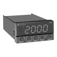
Newport Electronics INFINITY INFCR B Series Operator's Manual (56 pages)
C Programmable Digital RTD Meter
Brand:
Newport Electronics
| Category:
Measuring Instruments
| Size: 0 MB
Table of Contents
Table of Contents
4
Unpacking
9
1 Introduction
10
Safety Considerations
10
2 About the Meter
11
Description
11
Standard Features
11
Available Accessories
12
Table 2-1. Accessories and Add-Ons
12
Front of the Meter
13
Figure 2-1. Front-Panel with "Big" LED Display
13
Figure 2-2. Front-Panel with Standard LED Display
13
Rear of the Meter
16
Figure 2-3. Connector Label (AC-Powered and DC-Powered Detail)
16
Table 2-2. Rear Connector Description
17
Conditions Requiring Disassembly
18
3 Getting Started
19
Rating/Product Label
19
Main Board Power Jumpers
19
Figure 3-1. Main Board Power Jumpers (W1, W2, W3)
19
Figure 3-2. Main Board Jumper Positions (6 S2 Pins)
20
Figure 3-3. Upper Option Board Installation
20
Table 3-1. S3 Jumper Functions
21
Panel Mounting
22
Figure 3-4. Meter - Exploded View
22
Figure 3-5. Panel Cut-Out
22
Connecting Sensor Input
23
Figure 3-6. 2-Wire RTD Input Connection
23
Figure 3-7. 3-Wire RTD Input Connection
23
Figure 3-8. 4-Wire RTD Input Connection
23
Connecting Main Power
24
Figure 3-9. Main Power Connections - AC Powered Unit
24
Table 3-2. Main Power Connections - AC Powered Unit
24
Analog and Relay Output Connections
25
Figure 3-10. Main Power Connections - DC Powered Unit
25
Figure 3-11. Analog Output Connections
25
Figure 3-12. Relay Output Connections
26
Figure 3-13. Isolated Analog Output Connections
26
4 Configuring the Meter
27
Selecting the Input Type (Inpt)
27
Decimal Point Position (Dec.p)
27
Reading Configuration ("Rd.cf")
28
Color Configuration ("Colr")
28
Setpoint 1 Configuration (S1.Cf)
29
Setpoint 2 Configuration (S2.Cf)
30
Setpoint 1 Deadband (S1.Db)
30
Setpoint 2 Deadband (S2.Db)
31
Output Configuration (Ot.cf)
31
To Enable or Disable the Analog Output
31
To Select Analog Output as Current or Voltage
32
To Select Analog Output or Proportional Control
32
Proportional Band
33
Figure 4.1 Proportional Band
33
Manual Reset (M.rst)
34
Output Scale and Offset (Ot.s.o)
35
Rtd Temperature Offset (T.off)
37
Lock out Configuration (Lk.cf)
38
To Enable or Disable Setpoint Changes
38
To Enable or Disable the RESET Button in the Run Mode
38
To Enable Display's Program Version
38
BRIGHTNESS CONFIGURATION (Brit)
39
Tuning Proportional Controller (Tune)
39
Table 6-1. Menu Configuration
39
5 Display Messages
40
Table 5-1. Display Messages
40
6 Menu Configuration
41
Table 6-2. Front Panel Displays
43
Table 7-1. Setpoint Configuration Displays
44
Table 6-3. Run Mode Displays
45
7 Setpoint Configuration Displays
46
8 Specifications
47
Figure 8-1. Meter Dimensions
49
Table 9-1. Factory Preset Values
49
9 Factory Preset Values
50
Ce Approval Information
51
Advertisement
Advertisement
Related Products
Newport Electronics INFINITY INFCR Series
Newport Electronics INFINITY INFCDT
Newport Electronics INFCP-B Series
Newport Electronics INFINITY C
Newport Electronics IDP INFINITY D
Newport Electronics INFINITY INFCS-B Series
Newport Electronics INFINITY INFCS
Newport Electronics INFINITY Series
Newport Electronics INFINITY INF7
Newport Electronics INFINITY INFCS-011B
Newport Electronics Categories
Measuring Instruments
Controller
Thermometer
Monitor
Amplifier
More Newport Electronics Manuals
Login
Sign In
OR
Sign in with Facebook
Sign in with Google
Upload manual
Upload from disk
Upload from URL