Table of Contents
Advertisement
Quick Links
Wireless Meter Scanner & Controller
wi8xx-U
Operator's Manual
CHART
http://192.168.1.200
Save Current Graph
Min/Max Temperature
50
P1 Process
P2 Sensor 2
P3 Process
P4 Process
5
C/Div
P5 Process
P6 Process
P7 Process
P8 Sensor 8
0
Tue Feb 5 10:18:10 PDT 2008
http://www.newportUS.com/manuals
NEWPORT Electronics, Inc.
®
This datasheet has been downloaded from
wiSeries
48.0/41.0
C
1 Minute
(2 Seconds/Div)
1 Minute
1 Day
1 Week
Main Menu
1 Month
1 Year
hPa
1200
100%
A1 Ambient
A2 Sensor 2
A3 Ambient
A4 Ambient
90
10
hPa/Div
%/Div
A5 Ambient
A6 Ambient
A7 Ambient
A8 Sensor 8
300
0%
Tue Feb 5 10:19:10 PDT 2008
http://www.digchip.com
at this
page
Advertisement
Table of Contents

Related Manuals for Newport Electronics wi Series


Summary of Contents for Newport Electronics wi Series
- Page 1 Tue Feb 5 10:18:10 PDT 2008 Tue Feb 5 10:19:10 PDT 2008 1 Minute (2 Seconds/Div) 1 Minute 1 Day 1 Week Main Menu 1 Month 1 Year http://www.newportUS.com/manuals NEWPORT Electronics, Inc. ® This datasheet has been downloaded from http://www.digchip.com at this page...
- Page 2 European New Approach Directives. NEWPORT will add the CE mark to every appropriate device upon certification. The information contained in this document is believed to be correct but NEWPORT Electronics, Inc. accepts no liability for any errors it contains, and reserves the right to alter specifications without notice.
-
Page 3: Table Of Contents
TABLE OF CONTENTS Part 1 Introduction ..........1 Safety Considerations . - Page 4 4.3.7 Setup ......... .38 4.3.7.1 Input .
- Page 5 Figure 2.1 Front Panel Display ........5 Figure 2.2 Rear Panel Power and Output Connections .
- Page 6 Figure 4.26 HTTPget Example of Polling End Device ....59 Figure 4.27 ARP Commands and Responses ..... . .60 Figure 4.28 iLog Software Logging Data for End Device .
-
Page 7: Part 1 Introduction
PART 1 INTRODUCTION 1.1 Safety Considerations This device is marked with the international caution symbol. It is important to read this manual before installing or commissioning this device as it contains important information relating to Safety and EMC (Electromagnetic Compatibility). This instrument is a panel mount device protected in accordance with EN 61010-1:2001, electrical safety requirements for electrical equipment for measurement, control and laboratory. -
Page 8: Before You Begin
1.2 Before You Begin Inspecting Your Shipment: Remove the packing slip and verify that you have received everything listed. Inspect the container and equipment for signs of damage as soon as you receive the shipment. Note any evidence of rough handling in transit. -
Page 9: Description
1.3 Description (continued) The wireless sensors transmit up to four hundred feet 400’ (approx. 120 meters-- without obstructions or interference) to a wiSeries meter connected directly to an Ethernet network and the Internet. The wireless system complies with IEEE 802.15.4 operating at 2.4 GHz. -
Page 10: Figure 1.1 Temperature Wireless Monitor And Control System
1.3 Description (continued) DATALOGGING: The OPC Server software makes it easy to integrate the wiSeries wireless sensor system with many popular Data Acquisition and Automation programs offered by NEWPORT, OMEGA, Wonderware, iConics, Intellution, Rockwell Automation, and National Instruments, among others. PROGRAMMABLE COLOR DISPLAY: The wiSeries features patented programmable color displays. -
Page 11: Part 2 Hardware
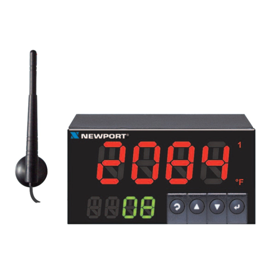
PART 2 HARDWARE 2.1 Physical Characteristics and Mounting 2.1.1 Front Panel Upper Display: Temperature Values Lower Display: Wireless Transmitter ID# 01 thru 08 Figure 2.1 Front Panel Display Table 2.1 Front Panel Enunciators Output 1 / Setpoint 1 / Alarm 1 indicator Output 2 / Setpoint 2 / Alarm 2 indicator °C °C unit indicator for Temperature... -
Page 12: Rear Panel
2.1.2 Rear Panel The rear panel connections are shown in Figure 2.2. ANTENNA RJ45 10BASE-T RESET LOCATION CONNECTION BUTTON INDICATORS Use copper conductors only for power connections POWER ETHERNET ACTIVITY NET LINK POWER / OUTPUT CONNECTOR OUTPUTS NOT USED RELAY PULSE ANALOG RELAY... -
Page 13: Dimensions
2.1.3 Dimensions 3.780 [96.00] 1.890 [48.00] 0.700 [17.78] 4.325 [109.85] PANEL THICKNESS 0.25 (6.4) MAX 0.03 (0.6) MIN PANEL CUTOUT 1/8 DIN Figure 2.3 Mounting Dimensions... -
Page 14: Assembly And Mounting
2.1.4 Assembly and Mounting 2.1.4.1 Panel Mounting Instruction 1. Using the dimensions from the panel cutout in Figure 2.3, cut an opening in the panel. 2. Remove sleeve from the rear of the case by removing thumbnuts. 3. Insert the case into the opening from the front of the panel, so the gasket seals between the bezel and the front of the panel. -
Page 15: Antenna Mounting Instruction
2.1.4.2 Antenna Mounting Instruction For best reception: connect the antenna directly to the rear of the meter, if the meter is not installed in a metal panel or enclosure. If the rear of the meter is behind a metal panel or in a cabinet, use a coaxial cable to position the antenna outside of the enclosure in the open air. -
Page 16: Disassembly Instruction
2.1.4.3 Disassembly Instruction If necessary, the board assembly may be removed from the front of the case housing. Warning: Disconnect ac power from the unit before proceeding. 1. Remove the board assembly from the case by pulling at the sides of the bezel. 2. -
Page 17: Electrical Installation
2.1.5 Electrical Installation 2.1.5.1 Power Connections Warning: Do not connect ac power to your meter until you have completed all output connections. This meter must only be installed by a specially trained electrician with corresponding qualifications. Failure to follow all instructions and warnings may result in injury! Connect the main power connections as shown below. -
Page 18: Wiring Outputs
2.1.5.2 Wiring Outputs This meter has two factory installed outputs. The SPDT Mechanical Relay, SPST Solid State Relay, Pulse and Analog Output Connection are shown below. Use copper conductors only for power connections Figure 2.8 a) Mechanical Relay and SSR b) Pulse and Analog Outputs Wiring Hookup Outputs Wiring Hookup... -
Page 19: Figure 2.9 Typical Applications
2.1.5.2 Wiring Outputs (continued) dc CONTROLLED SSR USED WITH TEMPERATURE CONTROLLER WITH dc VOLTAGE SSR DRIVER OUTPUT TEMPERATURE dc INPUT CONTROL LOAD CONTROLLER SIDE SIDE HEATER 0 or 5 Vdc, FAST BLOW TYPICALLY FUSE ac CONTROLLED SSR USED WITH TEMPERATURE CONTROLLER WITH MECHANICAL RELAY OUTPUT TEMPERATURE ac INPUT CONTROL... -
Page 20: Jumper Settings For Display Color Setup
2.1.5.3 Jumper Settings for Display Color Setup To change the color of the lower display follow the instructions below: 1. The unit should be removed from the panel and opened. Refer to Section 2.1.4.3 for assembly and disassembly instructions. 2. Locate S1 jumper, on the back side of the display board. Select the position for your color choice of Red, Green or Amber. -
Page 21: Dip Switches
2.1.5.4 Dip Switches To change the DIP switches, follow the instructions below: 1. The unit should be removed from the panel and opened. Refer to Section 2.1.4.3 for assembly and disassembly instructions. 2. Locate the 4 and 8 position DIP switches, on the top board. The Meter is shipped with all DIP switches in "OFF"... -
Page 22: Network Communications
2.2 Network Communication Interfaces 2.2.1 10Base-T RJ-45 Pinout The 10BASE-T Ethernet network (RJ-45) system is used in the Meter for network connectivity. The 10 Mbps twisted-pair Ethernet system operates over two pairs of wires. One pair is used for receiving data signals and the other pair is used for transmitting data signals. -
Page 23: Part 3 Network Configuration
PART 3 NETWORK CONFIGURATION 3.1 Ethernet (MAC) Address MAC (Media Access Control) address is your computer's unique hardware number. When you're connected to the LAN from your computer, a correspondence table relates your IP address to your computer's physical (MAC) address. -
Page 24: Dns
3.3 DHCP (continued) The Meter is shipped with DHCP disabled (factory default). If fixed or static IP address is desired, the DHCP must be disabled. The DHCP can be enabled by setting the DIP switch # 3 to the "ON" position Figure 3.2 4 Position DIP Switch Setting the Meter’s IP address to 0.0.0.0 will also enable DHCP. -
Page 25: Ip Address
3.5 IP Address Every active device connected to the TCP/IP network must have a unique IP address. This IP address is used to establish a connection to the Meter. Every computer using TCP/IP should have a unique 32-bit address which is divided into two portions, the network ID and the host ID. -
Page 26: Changing Tcp/Ip Properties On Your Computer
3.5.2 Changing TCP/IP Properties on Your Computer Go to your computer’s Control Panel then Network Connections. Pick the network with the proper Ethernet card. Right click and choose Properties Look for Internet Protocol, click on it and press Properties Figure 3.3 Network Connections Setup the IP address (in this case, 192.168.1.1) as shown below and press OK You can access the Meter’s Web Server via any internet browser... -
Page 27: Part 4 Network Operations
PART 4 NETWORK OPERATIONS This Meter can be used and configured in several ways, depending on user’s preference and network setup. It can be configured using a Web browser, like Internet Explorer. It can also be configured using the iConnect Configuration Software. -
Page 28: Iconnect Software
4.1 iConnect Software The Meter may also be assigned an IP Address by using the iConnect software. a) Download the iConnect software from the website listed in this manual. b) Install iConnect software on a networked PC. This software is compatible with Windows 95, 98, NT, 2000, and XP. -
Page 29: Figure 4.3 Accessing The Wireless System For Configuration
4.1 iConnect Software (continued) d) To access the Wireless System for Configuration: Click on the "View Webpage" button, you will access the Wireless System’s home page, refer to Section 4.3 for details. WIRELESS SENSOR HOME PAGE Figure 4.3 Accessing the Wireless System for Configuration... -
Page 30: Setting A New Ip Address Over The Network
4.2 Setting a New IP Address over the Network Besides using the iConnect software, you may use the Meter’s default IP address to access it and assign a new IP address to it. The Meter is shipped with a default IP address of 192.168.1.200 and Subnet Mask of 255.255.255.0. -
Page 31: Meter's Configurations And Operations
4.3 Meter’s Configurations and Operations Using a web browser, you should be able to view the Meter’s homepage. • Start your web browser. • From the browser you type http://wisxxxx using the last four-digits from the MAC address label located on the Meter (see Figure 3.1), if DHCP and DNS are used. -
Page 32: Power Up Meter
4.3 Meter’s Configurations and Operations (continued) LOGIN ADMINISTRATOR http://192.168.1.200 LOGIN http://192.168.1.200 ADMINISTRATOR Figure 4.6 LOGIN and ADMINISTRATOR Passwords There are 2 different access levels: 1. ADMINISTRATOR Password (administrator) allows certain groups and individual users to access and modify parameters without any restrictions. The default password is 00000000. -
Page 33: Get Readings From The End Device
4.3.2 Get Readings from the End Device Once you see the End Device’s LED blinking periodically, it means it is sending data which will appear on the "Readings" page. To view the data in a chart format, you can use the "Chart" page. Click on from the Home Page, the following page will appear, showing Readings... -
Page 34: Figure 4.8 Comma Separated Value Format
4.3.2 Get Readings from the End Device (continued) ID: End Device ID/address Sequence: Sequence number [0-255 ]. The Sequence number is incremented for each newly received data. Therefore, it indicates if the sensor is transmitting data successfully. Strength: It is the radio signal strength (0-100%), the higher the better. Success: 0-100%, a low success rate indicates a longer data delay, shorter battery lifetime and high network traffic. -
Page 35: Java Runtime Environment Setup
4.3.3 Java Runtime Environment Setup If your computer does not have Java installed, please download from java.sun.com. You can change the Java setting by clicking its icon in Control Panel. To load the applet, you have to enable the web browser and disable cache. -
Page 36: Java Runtime Environment 1.4 Setup Instructions
For Java 1.6.x.x it is similar to Java 1.5.x.x but there is no need to remove CACHE. 4.3.3.2 Java Runtime Environment 1.4 Setup Instructions 1. Go to your computer's Control Panel. Open the Java Plug-in 2. Select the "Cache" Tab Un-check the "Enable Caching"... -
Page 37: Browser Proxy Selection
4.3.3.3 Browser Proxy Selection Accessing Meter units within your internal network • Usually when the computer and Meters are on an internal network, you will not use Proxy server access. • You should un-check the "Use Browser Settings" option on the "Proxy" tab. Accessing Meter units using the internet •... -
Page 38: Java Policy
4.3.4 Java Policy To activate data logging and save graphs from the Java applets, it is necessary to create a Java Policy file and copy it onto a folder. Open a Notepad file and using the IP address of the Meter type the following: grant codeBase "http://192.168.1.200/"... -
Page 39: Figure 4.12 Java Policy
4.3.4 Java Policy (continued) 5)Change Java Applet’s Runtime Parameters found on the following path: Control Panel --> Java --> Java Control Panel --> Java Tab --> View Inside the box under the Java Runtime Parameters type the following: -Djava.security.policy=C:\0_JAVAPOLICY\java_policy.txt Click OK on the Java Runtime Settings window. Click Apply on the Java Control Panel window and then OK. -
Page 40: Chart
4.3.5 Chart Click on from the Home Page, the following page will appear. Chart The Java™ Applet graph displays Process Temperature and Ambient Temperature. It can be charted across the full span or within any narrow range (such as 20 to 30ºC). If a blank screen appears without any "java application running"... - Page 41 4.3.5 Chart (continued) Title: Meter’s name, assigned in "Network Setup" page. Save Current Graph: Save the current graph in PNG (Portable Network Graphics) format. The filename has the extension .png. Max/Min Temperature: Maximum and minimum temperature of the current graph. If a sensor is selected (trend line and sensor name turns bold), its most current temperature reading is shown here.
-
Page 42: Controller Setup
4.3.6 Controller Setup The Meter has two modes of operations. One is through the Front Panel Buttons (please refer to Front Panel Supplement for more details), and the other is by using the browser to configure the settings. Click on from the Home Controller Page. - Page 43 4.3.6 Controller Setup (continued) Below are the definitions of terms used in the Controller Setup page. A) Setup: Clicking on the options shown, allows user to modify the different parameters shown under this menu (see Section 4.3.7. Setup Page for more details). B) Monitor: Scrolling: If checked, the Meter will display data from all the End Devices.
-
Page 44: Setup
4.3.7 Setup This section is used to configure the Meter online. Click on the specific settings to change the parameters on that section 4.3.7.1 Input Control End Device ID: Insert the End Device ID number that will be used as input to control Filter: This option allows the user to specify the number of readings stored in the Digital Averaging Filter. -
Page 45: Setpoints & On/Off Control
4.3.7.2 Setpoints & On/Off Control Auto Setpoint Deviation: If "enabled", allows changes to Setpoint 1 to be made automatically to Setpoint 2. This mode is very helpful if the Temperature changes often. In Setpoint Deviation Mode, set SP2 a certain number of degrees or counts away from SP1--this relation remains fixed when SP1 is changed. -
Page 46: Figure 4.16 Setpoints & On/Off Control
4.3.7.2 Setpoints & On/Off Control (continued) SETUP http://192.168.1.200 Address SETUP Setpoints & On/Off Control Auto Setpoint Deviation Disabled Setpoint 1 Setpoint 2 Permanent Store On/Off 1 Disabled DeadBand Action Reverse On/Off 2 Disabled DeadBand Action Direct Update Cancel Main Menu Figure 4.16 Setpoints &... - Page 47 4.3.7.3 Alarms 1 & 2 Alarm 1 (or 2) Relay: to enable or disable (no alarm function) the alarms . Alarm 1 (or 2) Low: editable box for the low alarm value. Alarm 1 (or 2) High: editable box for the high alarm value. Active: If Above, Alarm condition triggered when the process variable is greater than the Alarm Hi Value (Low value ignored).
-
Page 48: Alarms 1 & 2
4.3.7.3 Alarms 1 & 2 (continued) SETUP http://192.168.1.200 Address SETUP Alarm 1 Alarm 1 Relay Enabled Alarm 1 Low Alarm 1 High Active Above Normally Open Latch Unlatched Absolute Absolute Alarm at Power On: Alarm could be Enabled triggered immediately by non-controlling end device at startup. -
Page 49: Analog Output Retransmission
4.3.7.4 Analog Output Retransmission This menu will appear only if you have the Analog Output Option installed in your Meter. SETUP http://192.168.1.200 Address SETUP Analog Output Retransmission Retransmission Enabled Voltage/Current Voltage Input Low Output Low 0.00 Min. 0V Input High 1000 Output High 10.00... -
Page 50: Display
4.3.7.5 Display This submenu allows the user to select the color of the display--green, red, amber. Screen Update: Editable box to enter the display time in seconds between each End Device. Normal: Choose the display color of temperature when it is in the normal stage. Alarm 1: Choose the display color of temperature when alarm 1 is true. -
Page 51: Figure 4.19B Display Menu (If Analog Output Option)
4.3.7.5 Display (continued) This version of the menu will appear only if you have the Analog Output Option installed in your Meter. SETUP http://192.168.1.200 Address SETUP Display Screen Update (seconds) Normal Green Alarm 2 Amber Update Cancel Main Menu Figure 4.19b Display Menu (if Analog Output Option) -
Page 52: Display Color Examples
4.3.7.5.1 Display Color Examples Example 1: Output 1 & Output 2 = SSR Alarm Setup: Absolute, Above, Alarm 2 HI Value " " = 200, A A L L R R . . H H Alarm 1 HI Value " "... - Page 53 4.3.7.5.1 Display Color Examples (continued) Example 3: Output 1 = Relay, Setpoint 1 = 300, Output 2 = Relay, Setpoint 2 = 200 Alarm 1 & 2 Setup: Deviation, Band, " " = 10 A A L L R R . . H H Color Display Setup: "...
-
Page 54: Passcode Id
4.3.7.6 Passcode ID To prevent unauthorized tampering with the setup parameters, the Meter provides protection by requiring the user to enter the ID Code before allowing access to subsequent menus of the Meter’s front panel. If the ID Code entered does not match the ID Code stored, the Meter responds with an error message and access to subsequent menus will be denied. -
Page 55: Network Setup
4.3.8 Network Setup Click on from the Home Page, the following page will appear. Network Setup NETWORK SETUP http://192.168.1.200 Address NETWORK SETUP General Secured Applet Title wiSeries Terminal Server TCP/UDP Command Server Type Forward CR Disable Number of Connections 1 Port 02000 Remote Access (Tunneling) 0.0.0.0... - Page 56 4.3.8 Network Setup (continued) A) General Secured Applet: If checked, the LOGIN password is required to open "Readings" and "Chart" pages. Title: Meter’s name [maximum of 16 alphanumeric characters], shows on the "Chart" and "Reading" pages. B) Terminal Server TCP/UDP*: The Meter supports TCP and UDP protocols (default is TCP). If UDP is selected, it can be configured either for Broadcast UDP or Directed UDP.
-
Page 57: End Device Setup
4.3.9 End Device Setup Click on from the Home Page, the following page will appear. End Device END DEVICE SETUP http://192.168.1.200 Address END DEVICE SETUP Name Update Network Units Remote Format EndChar Display Alarm 0000000F Lab 100 0000000F Lab 200 0000000F 0000000F ABCDEFGH... - Page 58 4.3.9 End Device Setup (continued) The End Device Setup Page is for configuring the End Device parameters such as Name and Update Rate. #: End Device ID/address configured on the End Device. Click on the number (1 to 8) to view device and modify End Device Parameters. Name: Name of an End Device, shows on the "Readings"...
-
Page 59: End Device Parameters
4.3.9.1 End Device Parameters (continued) END DEVICE PARAMETERS http://192.168.1.200 Address END DEVICE PARAMETERS End Device 1 Device Name: ABCDEFGH Update: Sensor1 Remote Display Format: 0000000F Remote End Char(Hex): 0x Offset(xxxx): Display: Alarm Sensor2 0000000F Remote Display Format: Remote End Char(Hex): 0x Offset(xxxx): Update Cancel... -
Page 60: Figure 4.24 Remote End Char
4.3.9.1 End Device Parameters (continued) Update (Seconds): How often this End Device is sending its data to the Meter. The default shown "update second" is 120 seconds. This update corresponds to the sampling rate configured by using the Configuration Wizard. For detailed steps on how to configure the sampling rate, please refer to Section 4.1 of the UWTC Manual. -
Page 61: Access Control
4.3.9.1 End Device Parameters (continued) If the end character for instance is 20 (Hex representation of space), the data will then appear as: T75F T74F If nothing is set for the "Remote End Char" field, the Meter will then forward the data to the LAN with no characters followed. - Page 62 4.3.10 Access Control (continued) Login Password: This allows users to access and modify all of the Wireless System Home Page menu items, except "Access Control", which requires an Administrator password. The default Login password is 12345678. This password can be up to 16 alpha-numeric case-sensitive characters. If there is no Login Password assigned (blank box) the Wireless System will not require a password to access and modify any of the menu items, except the "Access Control"...
-
Page 63: Telnet Setup
4.4 Telnet Setup In the "Network Setup" page, under the Terminal Server section, set the TCP Connections to 1 to 5 other than 0, and use a telnet emulation program to connect to the Meter (using Port 2000). The command can be sent to query the Meter and get a response back. -
Page 64: Httpget Program
4.5 HTTPget Program The Httpget software is used to send a single HTTP or TCP request to the Meter. In contrast, the telnet or Hyperterminal programs allow a continuous connection with multiple requests to be sent to the Meter. Generally HTTPget is used for simply programming an IP address to the Meter or for quickly obtaining a reading from a End Device. -
Page 65: Httpget And Arp To Setup Device Ip Address
where: -r –S are parameters needed for the the command string Command (See Table 4.1) 192.168.1.135 is an IP address 2000 is a socket port number -C1 closes the TCP connection after 1 second -q displays no error messages once the connection is closed Figure 4.26 HTTPget Example of Polling End Device #2,6,7 Table 4.2 Connector/Transmitter Types UWTC B Type TC... -
Page 66: Arp Protocol
4.6 ARP Protocol ARP is the Internet layer protocol responsible for matching or obtaining the MAC (hardware) address that corresponds to a particular IP address. The ARP command allows the user to view the current contents of the ARP cache of the local computer (residing on the same network). -
Page 67: Ilog Software
4.7 iLog Software This is an Excel application software that can log temperature from the Meter over the local network (Ethernet) or the internet. a) Download the iLog software from the website listed in this manual. b) Install iLog software on a networked PC. This software is compatible with Windows 95, 98, NT, 2000, and XP. -
Page 68: Table 4.3 Ilog Excel Applications
4.7 iLog Software (continued) Table 4.3 iLog Excel Applications The iLog application actually consists of several Excel files, though most supported devices can be accessed by the main iLog program. The main program is listed as "iLog", plus a version number, under the Start Menu program links (those links available by clicking the Start button on the Windows taskbar). -
Page 69: Mail Notifier Software
4.8 Mail Notifier Software For complete information of how to use the Mail Notifier software, click on the Help menu of the main window. The Mail Notifier software generates email notifications for alarm conditions. Users can be notified automatically of alarm conditions monitored via internet connections throughout the world. -
Page 70: Program Options Setup And Configuration
4.8.2 Program Options Setup and Configuration Complete program setup requires: • Entering a recipient for the email • Specifying connection details to MAPI services. • Defining alarms for devices, and selecting how and when the email will be active. Options Send To Email Setup Content Startup General Mail Server... -
Page 71: Device Settings And Configuration
4.8.3 Device Setting and Configuration The Meter and End Devices should first be configured and ready to use. Make sure to have the following settings in the "Network" web page of the Meter (Figure 4.20) . Number of Connections = 5 Port = 2000 (other values may be acceptable as long as Mail Notifier is setup with the same Port number) Then on the Mail Notifier Alarm Editor, set the BusAddress/DeviceID to match... -
Page 72: Sending Txt Messages To A Cell Phone
4.8.3 Device Setting and Configuration (continued) Alarm Editor Device Info (1 of 2) Server IP Address 192.168.1.200 Cancel Socket Number 2000 Help Bus Address/Device ID Description Src ID Dev1 SR##a Only Monitor Access Reading Cmd zRdgA to iServer device Alarm Configuration Alarm Type Alarm High Info Message... -
Page 73: Part 5 Environment/Operating Conditions
Part 5 ENVIRONMENT / OPERATING CONDITIONS The End Device and Meter are designed to be fixed mounted and operated in a clean and dry environment. Care should be taken to prevent the components of your wireless system from being exposed to moisture, toxic chemicals, extreme cold or hot temperature that are outside the specification listed in this manual. -
Page 74: Figure 5.1 Operation In Buildings
7. Where possible, try to ensure an uninterrupted line-of-sight between nodes. Avoid obscuring objects (e.g. metal pillars, posts, sign) near the antenna. A close object obscures a wider range of solid angle. 8. It is important to understand that the environment may change over time due to new equipment or machinery being installed, building construction, etc. -
Page 75: With Line-Of-Sight
5.2 With Line-of-Sight When installing the Meter it is important to position your device in such a way to optimize the antenna location within what’s known as the "Fresnel Zone". The Fresnel Zone can be thought of as a football-shaped invisible tunnel between two locations that provides a path for RF signals between the End Device and the Meter. -
Page 76: Without Line-Of-Sight
5.3 Without Line-of-Sight When line-of-sight is not possible, signal penetrates and is reflected by different objects to reach the destination. Therefore, it is important to learn about how these materials would affect signal propagation. Depending on the thickness, moisture content and angle of incidence, a wall may allow between 1% and 25% of the radio power to pass through. -
Page 77: Part 6 Specifications
PART 6 SPECIFICATIONS ON/OFF CONTROL OUTPUT 1 & 2 Relay: 250 Vac or 30 Vdc @ 3 A (Resistive Load), SPDT Solid State Relay (SSR): 20 to 265 Vac @ 0.05 to 0.5 A (Resistive Load); continuous DC Pulse: Non-Isolated; 10 Vdc @ 20 mA Analog Output (Output 1 only) Non-Isolated, 0 to 10 Vdc or 0 to 20 mA, 500 Ω... - Page 78 GENERAL Connection: Screw terminals Line Voltage/Power: 90 to 240 Vac +/-10%, 50 to 400 Hz*; 110 to 375 Vdc, equivalent voltage; 5 W * No CE compliance above 60 Hz Low Voltage/Power Option: 20 to 36 Vdc or 24 Vac** +/-10%; 4 W External power source must meet Safety Agency Approvals.
- Page 79 WIRELESS COMMUNICATION (continued) Radio Power Output: 100 mW (20 dBm), 10 mW (10 dBm) Limitations on Equivalent Isotropic Radiated Power (EIRP) levels in the European Community and other countries applies. An improper combination of power level can result in an EIRP above the allowed amount per regulations. See Appendix F.
-
Page 80: Part 7 Factory Preset Values
PART 7 FACTORY PRESET VALUES To set the Wireless and Ethernet settings back to Factory Default do the following to the DIP switches (see Figure 2.11). To set the Ethernet board to Factory Default settings: 1) Put the 4 position DIP switch #2 to ON position (it does not matter if the Meter is On or Off). - Page 81 Table 7.1 Factory Preset Values (continued) Setpoints & On/Off Control Auto Setpoint Deviation Disabled Setpoint 1 Setpoint 2 Permanent Store On/Off 1 Disabled Deadband Action Reverse On/Off 2 Disabled Deadband Action Reverse Alarm 1 Alarm 1 Relay Enabled Alarm 1 Low -100 Alarm 1 high 4000...
- Page 82 Table 7.1 Factory Preset Values (continued) Analog Output Retransmission Retransmission Enabled Voltage/Current Voltage Input Low Output Low 0.00 Input High 1000 Output High 10.00 Monitor Scrolling End Device ID Permanent Store Transmission Power PID (Network ID) 13106 (version x.x) Channel Transmission Power 20 dBm Misc...
- Page 83 Table 7.1 Factory Preset Values (continued) End Device Setup Name Update Network Units Remote Format End Char Display Alarm 0000000F 1 ABCDEFGH 0000000F 0000000F 2 ABCDEFGH 0000000F 0000000F 3 ABCDEFGH 0000000F 0000000F 4 ABCDEFGH 0000000F 0000000F 5 ABCDEFGH 0000000F 0000000F 6 ABCDEFGH 0000000F 0000000F...
-
Page 84: Appendix Aglossary
APPENDIX A GLOSSARY User of this manual should be familiar with following definitions: ARP (Address Resolution Protocol) is a protocol for mapping an Internet Protocol address (IP address) to a physical machine address that is recognized in the local network. For example, the IP address in use today is an address that is 32-bits long. In an Ethernet local area network, however, addresses for attached devices are 48-bits long. - Page 85 Appendix B IP Address An IP address is a unique 32-bit address assigned to a computer and includes: • A network ID number identifying a network. • A host ID number identifying a computer on the network. All IP addresses have been divided into three smaller groups (classes) A, B and C •...
-
Page 86: Appendix Cip Netmask
Appendix C IP Netmask IP Netmask or Subnet Mask is a 32-bit pattern of ones and zeros used to determine network portion of an IP address from the host portion of the IP address. Subnet mask is a network ID that is created by borrowing bits from host portion of IP address and using them as part of a network ID. -
Page 87: Appendix Dascii Chart
Appendix D ASCII Chart ASCII Binary ASCII Binary Char No Parity Char No parity 00000000 01000000 00000001 01000000 00000010 01000010 00000011 01000011 00000100 01000100 00000101 01000101 00000110 01000110 00000111 01000111 00001000 01001000 00001001 01001001 00001010 01001010 00001011 01001011 00001100 01001100 00001101 01001101 00001110... - Page 88 Appendix D ASCII Chart Continuation 00101111 01101111 00110000 01110000 00110001 01110001 00110010 01110010 00110011 01110011 00110100 01110100 00110101 01110101 00110110 01110110 00110111 01110111 00111000 01111000 00111001 01111001 00111010 01111010 00111011 01111011 < 00111100 01111100 00111101 01111101 > 00111110 01111110 00111111 01111111 ASCII Control Codes ASCII Dec Hex Ctrl Key...
-
Page 89: Appendix E Ilog Error Messages
Appendix E iLog Error Messages Error # Description Note -8003 User stopped logging readings. -10005 Failed to find the Meter. Ethernet cable is disconnected, iServer is powered off, connections across the firewall require longer “connection to socket time out” setting. -10006 Windows socket was closed. - Page 90 Appendix F Warnings and Regulatory Information (continued) The following alert sign indicates that there are restrictions on usage of the equipment in regards to power limitations on Equivalent Isotropic Radiated Power (EIRP) levels in the European Community. The following are user restrictions: •...
- Page 91 Warranty/Disclaimer NEWPORT Electronics, Inc. warrants this unit to be free of defects in materials and workmanship for a period of one (1) year from the date of purchase. In addition to NEWPORT’s standard warranty period, NEWPORT Electronics will extend the warranty period for one (1) additional year if the warranty card enclosed with each instrument is returned to NEWPORT.
- Page 92 Tel: +44 161 777 6611 • FAX: +44 161 777 6622 Toll Free: 0800 488 488 • www.newportuk.co.uk • e-mail:sales@newportuk.co.uk Newport Electronics B.V. - Benelux TEL: +31 20 3472121 • FAX: +31 20 6434643 Toll Free: 0800 0993344 • www.newport.nl • e-mail: info@newport.nl Newport Electronics spol s.r.o.
Need help?
Do you have a question about the wi Series and is the answer not in the manual?
Questions and answers