
Related Manuals for Newport Electronics 558B


Summary of Contents for Newport Electronics 558B
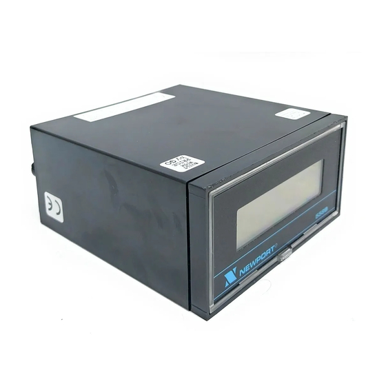
- Page 1 558B CURRENT LOOP INDICATOR Operator’ s Manual ® NEWPORT Electronics, Inc. http://www.newportUS.com/manuals...
- Page 2 Additional products from NEWPORT Electronics, Inc. ® Counters Rate Meters Frequency Meters Timers PID Controllers Totalizers Clock/Timers Strain Gauge Meters Printers Voltmeters Process Meters Multimeters On/Off Controllers Soldering Iron Testers Recorders pH pens Relative Humidity pH Controllers Transmitters pH Electrodes...
-
Page 3: Table Of Contents
Main Board Jumper Locations ........8 Figure 7-1 Wiring Diagram for 558B Usage for FM (Factory Mutual) ... . 11... - Page 4 UNPACKING INSTRUCTIONS Remove the Packing List and verify that you have received all equipment, including the following: DESCRIPTION Current Loop Meter Indicator with all applicable connnectors attached. Owner's Manual Factory Setup Label If you have any questions about the shipment, use the phone number for the Customer Service Department nearest you.
-
Page 5: General Information
Five 12.7 mm (0.5 in) high liquid crystal 7-segment digits are used to display ±1999 active counts plus one or two dummy right-hand zeros. The 558B displays from -1999 to 1999 counts with the option of one or two dummy right-hand “0” digits. Zero suppression or elevation capability exceeds full scale. -
Page 6: Specifications
2.0 SPECIFICATIONS 2.1 INPUT Current 1-5 mA, 4-20 mA or 10-50 mA Protection 200 mA max forward and 1000 mA max reverse Voltage Drop 2.5 V max forward and 1.2 V max reverse Span Range 100 to 2000 counts continuous adjustment with a multiturn potentiometer Zero Range The multiturn zero potentiometer can displace... -
Page 7: Display
2.4 DISPLAY Type 7-segment LCD Color Black digits with white background Symbols -1.8.8.8.0.0, 12.7 mm (0.5 in) height Polarity Minus sign Overrange Three least-significant digits blank Extra digits One or two dummy right-hand zeros, jumper-selectable Decimal points Four positions, jumper-selectable Lifetime (to 2:1 contrast ratio) More than 30,000 hours Temperature derating... -
Page 8: Mechanical Assembly And Installation
3.0 MECHANICAL ASSEMBLY AND INSTALLATION 3.1 SAFETY CONSIDERATIONS To ensure safe operation, follow the guidelines below: VISUAL INSPECTION: Do not attempt to operate the instrument if damage is found. SIGNAL WIRING: Insert the proper plus and minus signal wires into the plug-in screw-clamp connector terminals marked plus and minus. -
Page 9: Installation/Removal
3.3 INSTALLATION/REMOVAL The 558B is housed in a 1/8 DIN case. The electronic circuitry can be installed or removed from the front and is attached to the case with two M4 screws through the rear panel. Panel Mounting Remove the two thumbnuts on the rear of the case. -
Page 10: Signal Input Connections (P3)
1.89 [48.0] 3.78 [96.0] 7.9 [0.31] MAX CASE 3.50 [88.9] SLEEVE 4.15 [105.4] TOP VIEW SIDE VIEW PANEL THICKNESS: 0.25 [6.4] MAX 0.03 [0.8] MIN 0.06 1.772 +.024/-.000 [1.5] [45.00 +0.61/-0.00] 4 PLCS 3.622 +.032/-.000 [92.00 +0.81/-0.00] PANEL CUT-OUT NOTES: DIMENSIONS ARE IN INCHES [MILLIMETERS]. Figure 3-2. -
Page 11: Configuration
5.0 CONFIGURATION The standard 558B meter is factory-configured for an input of 4-20 mA to display 00.0 to 100.0. Field configuration for input current range, decimal point location, dummy right-hand zero digit, coarse zero range selection, and reverse span slope may be done by relocating internal push-on jumpers and adjusting the span and zero potentiometers. -
Page 12: Figure 5-1 Main Board Jumper Locations
SPAN ADJ. ZERO ADJ. Figure 5-1 Main Board Jumper Locations... -
Page 13: Customer Configuration And Calibration
6.0 CUSTOMER CONFIGURATION AND CALIBRATION Use this procedure to determine the configuration of the 558B customized setup. The procedure is general; customers can specify any two current inputs and their corresponding digital readings. Pin-groups are shown in Figure 5-1. 6.1 FORMULA Base all your calculations on either the 1-5, 4-20 or 10-50 mA range. -
Page 14: Configuration Procedures
6.2 CONFIGURATION PROCEDURES Remove all push-on jumpers. For an input current range of 1-5 mA, no jumper is required. For 4-20 mA input, install a push-on jumper at S1-H. For 10-50 mA input, install a push-on jumper at S1-J. If N2 (Section 6.1) is less than N1, reverse the signal polarity by removing jumpers from S1-B and S1-C and reinstalling jumpers at S1-A and S1-D. -
Page 15: Wiring Diagram
Interconnecting Cable must not exceed the values specified for the barrier in use. The electrical circuit in the Hazardous Area must be capable of withstanding without breakdown an A.C. test voltage of 500V R.M.S. to Earth or frame for one minute. Figure 7-1 Wiring Diagram for 558B Usage for FM (Factory Mutual) - Page 16 Warranty/Disclaimer NEWPORT ELECTRONICS, INC. warrants this unit to be free of defects in materials and workmanship for a period of one (1) year from date of purchase. In addition to NEWPORT’s standard warranty period, NEWPORT ELECTRONICS will extend the warranty period for one (1) additional year if the warranty card enclosed with each instrument is returned to NEWPORT.
- Page 17 Postbus 8034 • 1180 LA Amstelveen • The Netherlands TEL: +31 20 3472121 • FAX: +31 20 6434643 Toll Free: 0800 0993344 • www.newport.nl • e-mail: info@newport.nl Newport Electronics spol s.r.o. Frystatska 184, 733 01 Karviná • Czech Republic TEL: +420 59 6311899 • FAX: +420 59 6311114 Toll Free: 0800-1-66342 •...
- Page 18 X-ON Electronics Largest Supplier of Electrical and Electronic Components Click to view similar products for manufacturer: newport Other Similar products are found below : BDS1 BDT1 WTK-14-36/N 5TC-TT-J-24-72 TXDIN70 OTP-U-F 5SC-TT-K-30-36 WTK-8-24/N OTP-U-M TPJ-U-F 5TC-TT-J-24-50/N 5SC-TT-T-30-72 SMTC-AL-P SMPW-CC-T-M MPJ-K-F-ROHS...
Need help?
Do you have a question about the 558B and is the answer not in the manual?
Questions and answers