
Related Manuals for Newport Electronics INFINITY INFCDT


Summary of Contents for Newport Electronics INFINITY INFCDT
- Page 1 INFCDT INFINITY ® C Differential Temperature Meter with Thermocouple Operator’s Manual NEWPORT Electronics, Inc. http://www.newportUS.com/manuals...
- Page 2 European New Approach Directives. NEWPORT will add the CE mark to every appropriate device upon certification. The information contained in this document is believed to be correct but NEWPORT Electronics, Inc. accepts no liability for any errors it contains, and reserves the right to alter specifications without notice.
-
Page 9: Section 1. Introduction
SECTION 1. INTRODUCTION 1.1 UNPACKING Remove the Packing List and verify that all equipment has been received. If there are any questions about the shipment, use the phone numbers listed on the back cover to contact the Customer Service Department nearest you. Upon receipt of shipment, inspect the container and equipment for any signs of damage. -
Page 10: Safety Considerations
1.2 SAFETY CONSIDERATIONS This device is marked with the international caution symbol. It is important to read this manual before installing or commissioning this device as it contains important information relating to Safety and EMC (Electromagnetic Compatibility). This instrument is a panel mount device protected in accordance with EN 61010-1:2001, electrical safety requirements for electrical equipment for measurement, control and laboratory. -
Page 11: Section 2. About The Meter
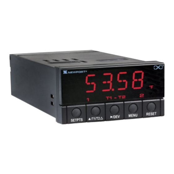
SECTION 2. ABOUT THE METER 2.1 DESCRIPTION The Differential Temperature meter with thermocouple is a value packed indicator/ controller. Four full digits allow for an accurate display of your temperature. Select from J, K, T or DIN J thermocouple types. Your meter may be a basic indicator or it may include analog output or dual relay output. -
Page 17: Back Of The Meter
2.5 BACK OF THE METER Figure 2-2 shows the connector label mounted at the top of the meter housing. Table 2-2 gives a brief description of each connector at the back of the meter. Figure 2-2 Connector Label (ac power with dc detail) -
Page 23: Panel Mounting
3.3 PANEL MOUNTING CONNECTOR LABEL PRODUCT CASE LABEL GASKET FRONT BEZEL Figure 3-3 Meter - Exploded VIew 1. Cut a hole in your panel, as shown in Figure 3-3. For specific dimensions refer to Figure 3-4. 2. Insert the meter into the hole. - Page 57 SECTION 13. SPECIFICATIONS (continued) ALARM OUTPUTS 2 Form "C" on/off relays. Configurable for latched and (if applicable) unlatched by software. Max current: 5 AMPS, resistive load Max voltage: 250 Vac or 30 Vdc ENVIRONMENT ~ AC units 115/230 V~(AC) + 10%, 50/60 Hz 7 W max, power consumption (Non-Isolated Analog Out) 8 W max, power consumption (Isolated Analog Out) DC units...
-
Page 58: Side View
SECTION 13. SPECIFICATIONS (continued) 48,0 (1.89) 96,0 (3.78) FRONT BEZEL 20,3 (.80) RETAINER CASE REAR COVER TOP VIEW SIDE VIEW Figure 13-1 Meter Dimensions... -
Page 59: Section 14. Factory Preset Values
SECTION 14. FACTORY PRESET VALUES Table 14-1. Factory Preset Values MENU ITEM FACTORY PRESET VALUES INPT Input Type: K.TC (Type K T/C) DEC.P Decimal Point Position: FFF.F RD.CF Reading Configuration: R.1=F (Fahrenheit) R.2=D (Shows deviation in “RUN” mode) S1.CF Setpoint 1 Configuration: S.1=A (Setpoint is active above) S.2=U (Setpoint is unlatched) S.3=0 (Setpoint 1 assigned to T1 - T2) - Page 60 CE APPROVALS INFORMATION This product conforms to the EMC directive 89/336/EEC amended by 93/68/EEC, and with the European Low Voltage Directive 72/23/EEC. Electrical Safety EN61010-1:2001 Safety requirements for electrical equipment for measurement, control and laboratory. Double Insulation Pollution Degree 2 Dielectric withstand Test per 1 min •...
- Page 63 Warranty/Disclaimer NEWPORT Electronics, Inc. warrants this unit to be free of defects in materials and workmanship for a period of one (1) year from the date of purchase. In addition to NEWPORT’s standard warranty period, NEWPORT Electronics will extend the warranty period for four (4) additional years if the warranty card enclosed with each instrument is returned to NEWPORT.
- Page 64 Tel: +44 161 777 6611 • FAX: +44 161 777 6622 Toll Free: 0800 488 488 • www.newportuk.co.uk • e-mail:sales@newportuk.co.uk Newport Electronics B.V. - Benelux TEL: +31 20 3472121 • FAX: +31 20 6434643 Toll Free: 0800 0993344 • www.newport.nl • e-mail: info@newport.nl Newport Electronics spol s.r.o.
Need help?
Do you have a question about the INFINITY INFCDT and is the answer not in the manual?
Questions and answers